
5.3 Rare-Earth Magnets: Advancements and Applications
The first generation of rare - earth iron permanent magnets, dating from the 1960s, were binary alloys of cobalt and samarium having the \(\text{CaCu}_{5}\) structure. \(\text{SmCo}_{5}\) has a huge anisotropy field, close to 40 T, which makes the development of coercivity rather easy in this material. The related binary alloy with the \(\text{Th}_{2}\text{Zn}_{17}\) structure has insufficient anisotropy to permit the achievement of high coercivity, but a second generation of \(\text{Sm - Co}\) - based magnets was developed in the 1970s with a composition intermediate between 1:5 and 2:17, wherein there is extensive chemical substitution of Fe, Cu and Zr for Co. These alloys show a nanoscale intergrowth of the two structure types which leads to coercivity by domain - wall pinning. \(\text{Sm - Co}\) magnets exhibit high Curie temperatures and the temperature dependence of the magnetization can be reduced to a negligible value by substituting some heavy rare earth such as gadolinium for samarium. These features guarantee that \(\text{Sm - Co}\) magnets will continue to find applications where elevated temperatures, up to 300 °C, are involved or when a highly stable magnetic field is required in an environment of varying temperature. For other purposes they have been superseded by the third generation of rare - earth magnets, based on \(\text{Nd}_{2}\text{Fe}_{14}\text{B}\).
The basic idea of using 4f - 3d intermetallics in permanent magnets is to combine the best features of both components. The rare - earth atoms offer strong uniaxial magnetocrystalline anisotropy when they occupy sites of appropriate symmetry. The 3d atoms, iron and cobalt, contribute a large magnetization with a useful Curie temperature. When all attributes are preserved in the compound, a useful permanent magnet is possible.
Alloying 4f elements with 3d elements tends to reduce the 3d magnetic moment by admixture of non - magnetic 5d/6s states into the 3d band (section 2.4.2). Furthermore, rare - earth elements dilute the ferromagnetic magnetization because their atomic volume is roughly three times that of iron or cobalt whereas the light rare - earth atomic moment is no more than twice that of cobalt or half as great again as that of iron (table 2.4). Relative atomic sizes are illustrated in figure 5.15.
The heavy rare earths Dy and Ho have moments as high as \(10\ \mu_{\text{B}}\), but these tend to couple antiparallel to the 3d spins in a ferrimagnetic structure. The 3d - 4f exchange coupling involves the atomic spins but it is mostly mediated by the rare - earth 5d electrons which have significant on - site overlap with the 4f shell and inter - site overlap with the 3d electrons of a neighbouring
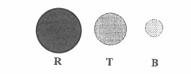
Figure 5.15. Light 4f atoms (R, Sm, Nd), late atoms T (Fe, Co) and 2p interstitial atoms B (B, N, C) drawn roughly to scale.
cobalt atom. The 3d and 5d spins couple antiparallel as the 5d electrons can extend into unoccupied \(3d_{\downarrow}\) states. The 4f - 5d coupling is ferromagnetic. Hence the net result is that the 3d spin moment couples antiparallel to the moment of the heavy rare earth, where by Hund's third rule \(L\) and \(S\) are parallel, but it couples parallel to the moment of a light rare earth, where \(L\) and \(S\) are antiparallel and the moment is of mainly orbital character (figure 2.11).
Restrictions on which binary intermetallics are appropriate for permanent magnets are quite severe. They must be rich in the 3d element, with a uniaxial crystal structure and a high Curie point. The 4f partner should be a magnetic light rare earth (\(\text{Pr}\), \(\text{Nd}\) or \(\text{Sm}\)). The others are either non - magnetic (\(\text{Y}\), \(\text{La}\), \(\text{Eu}\)), unstable, or else possess a spin moment \(S=(1/2)\) so small that it couples feebly to the 3d spin (\(\text{Ce}\)). Yttrium intermetallics are useful model compounds for investigating the 3d magnetism alone. The resultant anisotropy from the 3d and 4f sublattices must be strongly easy - axis. There is actually no binary \(\text{R - Fe}\) compound which satisfies all these conditions and only a few \(\text{R - Co}\) compounds.
Samarium-Cobalt Magnets: Strength, Stability, and Uses
The \(\text{Sm - Co}\) binary phase diagram is shown in figure 5.16. The two compounds richest in cobalt are \(\text{SmCo}_{5}\) and \(\text{Sm}_{2}\text{Co}_{17}\). Each of them has a uniaxial structure and a high Curie point. The hexagonal structure of \(\text{SmCo}_{5}\) (\(\text{CaCu}_{5}\) - type) is rather simple with alternating planes of cobalt at \(z = 0\) in \(3g\) sites and planes of cobalt and samarium at \(z = 1/2\) in \(2c\) and \(1a\) sites, respectively (figure 1.16). The structure resembles that of hcp Co; samarium is surrounded by a hexagonal prism of cobalt. Variants exist where some of the \(2c\) cobalt is replaced by another atom such as boron, in \(\text{SmCo}_{4}\text{B}\), for example. The 1:5 structure does not form with iron.
The structure of \(\text{Sm}_{2}\text{Co}_{17}\) is derived from that of \(\text{SmCo}_{5}\) by replacing one third of the Sm by dumbbell pairs of cobalt atoms. There are two variants of the structure, the rhombohedral form where the planes containing the dumbbells have
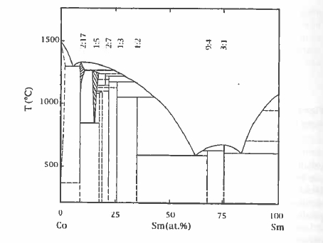
Figure 5.16. The Sm-Co equilibrium phase diagram
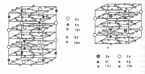
Figure 5.17. Comparison of the rhombohedral and hexagonal variants of \(\text{Sm}_{2}\text{Co}_{17}\) (rhombohedral \(\text{Th}_{2}\text{Zn}_{17}\) - type or hexagonal \(\text{Th}_{2}\text{Ni}_{17}\) - type). The large circles represent Samarium. The dumbbells which replace the Sm are highlighted. Sites occupied by interstitial nitrogen in \(\text{Sm}_{2}\text{Fe}_{17}\text{N}_{3}\) are also indicated by small black circles.
stacking sequence ABCABC... and the hexagonal form where the sequence is ABAB.... Both variants are illustrated in figure 5.17. \(\text{Sm}_{2}\text{Co}_{17}\) usually
Table 5.10. 3d moments in some rare - earth intermetallic compounds (\(\mu_{\text{B}}/\text{atom}\)) at \(T = 0\).
| YCo5 | 2c 1.7 | 3g 1.6 | ||||
| Y5Co17 | 4f 1.7 | 4g 1.5 | 12j 1.5 | 12k 1.5 | ||
| Y2Fe17 | 4f 2.5 | 4g 1.9 | 12j 2.2 | 12k 2.0 | ||
| Y2Fe17N3 | 4f 2.7 | 4g 2.5 | 12j 2.0 | 12k 2.6 | ||
| Y2Fe14B | 4c 1.9 | 4e 2.2 | 8j12.4 | 8j22.8 | 16k 2.2 | 16k 2.3 |
| Y(Fe11Ti) | 8f 1.5 | 8i 2.0 | 8j 1.8 |
crystallizes in the rhombohedral form. Both variants of the 2:17 structure type exist for R - Fe intermetallics.
Properties of Sm - Co magnets have been reviewed by Sinha (1988, 1991) and Kumar (1988).
Intrinsic Magnetic Properties of Sm - Co compounds
The average zero - temperature cobalt moment is reduced by the presence of the rare earth from the pure Co value of \(1.7\ \mu_{\text{B}}\) to \(1.5\ \mu_{\text{B}}\) in \(\text{SmCo}_{5}\). The cobalt moments on the two sites are a little different (table 5.10) and measurements of the nuclear quadrupole interaction by \(^{59}\text{Co}\) nuclear magnetic resonance indicate that a larger orbital moment (about \(0.3\ \mu_{\text{B}}\)) resides on 2c sites, where it makes a substantial contribution to the uniaxial anisotropy.
The intrinsic magnetic properties of \(SmCo_5\) are compared with those of \(YCo_5\) in table 5.1.1. The anisotropy of \(YCo_5\) is already substantial, indicating that 40% of the anisotropy energy \(K_1\) of \(SmCo_5\) is due to cobalt and 60% is due to samarium. The point symmetry of the la - samarium site is 6/mmm, so two terms \(B_2^0\tilde{O}_2^0 + B_4^0\tilde{O}_4^0\) suffice to describe the crystal - field interaction for the \(J = 5/2\) ground state. The first of these is dominant at room temperature. Since \(A_{2}^{0}\) is negative (\(-200\ K\ a_{0}^{-2}\)), only elements with a quadrupole moment of positive sign will contribute to the uniaxial anisotropy; Sm is the only suitable light rare earth (table 2.7).
The related compound \(\text{Sm}_{2}\text{Co}_{17}\) has a larger magnetization and Curie temperature on account of the lesser amount of rare earth in the structure. The dumbbell substitution has a dramatic effect on the cobalt anisotropy, destroying the easy - axis character and making \(\text{Y}_{2}\text{Co}_{17}\) weakly easy - plane. The samarium contribution is also weaker in 2:17 than in 1:5 due to a reduced crystal - field interaction at the 6c sites. Unlike \(\text{SmCo}_{5}\), it is difficult to develop adequate coercivity for a permanent magnet in pure \(\text{Sm}_{2}\text{Co}_{17}\) because the anisotropy is a factor of five weaker.
Chemical substitution in the 1:5 or 2:17 compounds modifies their intrinsic magnetic properties. Replacing the Sm by another rare earth has relatively little effect on the Curie temperature of the cobalt compounds (figure 5.18), but it does influence the substantially lower Curie temperatures of the iron
Table 5.11. Intrinsic magnetic properties of R - Co compounds.
| a (pm) | c (pm) | TC (K) | μ0Ms (T) | K1 (MJ m-3) | μ0H0 (T) | A02 (K a0-2) | κ | |
|---|---|---|---|---|---|---|---|---|
| YCo5 | 494 | 398 | 987 | 1.06 | 6.5 | 15.4 | 2.7 | |
| PrCo5 | 502 | 399 | 912 | 1.20 | 8.1 | 16.9 | 2.7 | |
| SmCo5 | 499 | 397 | 1020 | 1.07 | 17.2 | 38.6 | -200 | 4.4 |
| GdCo5 | 498 | 397 | 1014 | 0.36 | 4.6 | 32.1 | 9.4 | |
| Y2Co17 | 834 | 1219 | 1167 | 1.25 | -0.4 | -0.8 | — | |
| Pr2Co17 | 843 | 1227 | 1171 | 1.38 | -0.6 | -1.1 | — | |
| Sm2Co17 | 838 | 1221 | 1190 | 1.22 | 3.3 | 6.5 | -108 | 1.6 |
| Gd2Co17 | 837 | 1218 | 1209 | 0.75 | -0.5 | -1.7 | — |
compounds. This is because the R - Co exchange is negligible compared with the strong Co - Co exchange (\(J_{\text{Co - Co}}\approx100\ K\)), but the R - Fe exchange is significant compared to the Fe - Fe exchange, especially near the middle of the rare - earth series (section 2.3.2.7). Changing the rare earth has a big influence on the magnetization due to the different moments of the different rare earths and the change from ferromagnetic R - T order for the light rare earths to ferrimagnetic order for the heavy ones (figure 2.3.2). Furthermore, the relatively weak R - Co exchange means that the temperature dependences of the R and Co sublattices are quite different (figure 5.19). In compounds with heavy rare earths, a compensation point may occur, as in the rare - earth iron garnets. The different temperature dependences of the R and Co sublattices permit adjustment of the temperature dependence of the net magnetization to zero over a desired temperature range.
The magnetization can also be modified by substituting another 3d element for cobalt. The \(RCo_{5}\) and \(R_{2}Co_{17}\) compounds are strong ferromagnets in the sense that the 3d spins of both the Fe and Co atoms bear the maximum moment consistent with their electronic configuration, about \(1.5\ \mu_{\text{B}}\). Only iron has a larger moment. It is insoluble in \(SmCo_{5}\), but there is a complete range of solid solubility with \(Sm_{2}Fe_{17}\). Commercial 2:17 magnets contain iron to boost their magnetization.
The huge uniaxial anisotropy of the \(SmCo_{5}\) compound means that substitutions that reduce the anisotropy can be tolerated provided they offer a corresponding benefit. The light rare earths Pr or Nd increase the magnetization since their moment is greater than that of Sm. Mischmetal, a mixture of unseparated rare earths derived from the ore, reduces the cost. In \(Sm_{2}Co_{17}\) the problem is rather to increase the anisotropy, which can be achieved by replacing the 6c cobalt dumbbells, which destroy uniaxial anisotropy of the cobalt sublattice, by a non - magnetic atom such as Zr. Optimized 2:17 magnets have the formula \(Sm(Co, Fe, Zr, Cu)_{7 - 8}\).
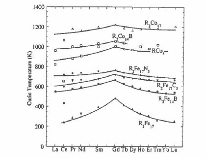
Figure 5.18. Curie temperatures of some intermetallic compounds.
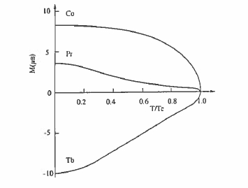
Figure 5.19. The schematic temperature dependence of the sublattice magnetization of the transition metal (Co) and the light (Pr) or heavy (Tb) rare earth in an \(RCo_{5}\) intermetallic.
Microstructure and Coercivity of Sm - Co Magnets
Favourable intrinsic magnetic properties have to be translated into useful hysteresis by a suitable microstructure. Micrometre - sized particles exhibit nucleation - controlled hysteresis when they are free of defects larger than the
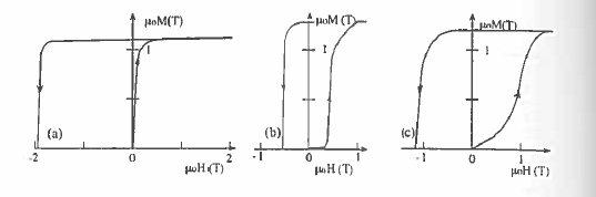
Figure 5.20. Initial magnetization curves and second - quadrant hysteresis loops for (a) \(\text{SmCo}_{5}\), (b) \(\text{Sm}_{2}\text{Co}_{17}\) and (c) high - coercivity \(\text{Sm}_{2}\text{Co}_{17}\) magnets. (a) is typical of a nucleation - type magnet, (b) of a pinning - type magnet and (c) of a magnet with a distribution of pinning centres.
domain - wall width \(\delta_{\text{B}}\), which is 4 nm for \(\text{SmCo}_{5}\). The coercivity mechanism is similar to that discussed for hexagonal ferrites in section 5.1.3.2. Typical crystallites in \(\text{SmCo}_{5}\) magnets are about 5 \(\mu\text{m}\) in size so they are usually multidomain in the unmagnetized state since \(R_{\text{sd}} = 0.8\ \mu\text{m}\). However, the critical single - domain radius \(R_{\text{sd}}\) is an equilibrium property which is not really relevant in discussing coercivity (section 3.4). The walls move freely across a crystallite in an applied field and saturation is readily achieved (figure 5.20(a)). Once the domain structure has been eliminated, the magnetization remains saturated until a large reverse field creates nuclei from which reverse domains propagate and the magnetization switches. Reducing the material to a fine powder confines the defects that act as nucleation centres to just a few grains, which may reverse without affecting all the others. Despite a coercivity which can reach high values of 2 T or more, the \(\text{SmCo}_{5}\) magnets are rather easy to magnetize. They are typical nucleation - type magnets. The defects which act as nucleation centres for reverse domains are mostly associated with the surface of milled powder particles, so coercivity can be increased by annealing or etching away the surface layer. Figure 5.21 illustrates the domain reversal in \(\text{SmCo}_{5}\). The energy products are close to 180 kJ m-3.
A different coercivity mechanism applies when some copper is substituted for cobalt. Here, a homogeneous Cu - rich precipitate appearing inside the grains of the 1:5 phase impedes domain - wall movement. Provided the homogeneously distributed defects are on the scale of the domain - wall width, the walls are pinned at the defects and an initial magnetization curve of type (b) in figure 5.20 results.
Pinning - type coercivity (section 3.3.4.4) was fully exploited in the second - generation \(\text{Sm - Co}\) magnets which have a composition close to \(\text{Sm}(\text{CoFeCuZr})_{x}\) where \(x\approx7.2 - 8.5\). Iron is added to increase the remanence and Cu and Zr help form the required microstructure. The composition is intermediate
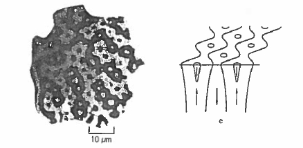
Figure 5.21. Kerr effect micrographs illustrating domain reversal in the second quadrant for an \(\text{SmCo}_{5}\) sintered magnet (Bachmann 1971).
between 1:5 and 2:17, and the main feature of the microstructure is a network of small (\(\approx100\ nm\)) rhombohedral 2:17 - structure cells separated by thin (\(\approx10\ nm\)) boundary layers with the 1:5 structure which serve to pin the domain walls. With suitable heat treatment, lamellae of a platelet phase form which incorporate much of the Zr in the hexagonal 2:17 structure. All three phases are crystallographically coherent, with a common \(c\) - axis. There is great scope in this system for varying the composition and microstructure to yield desired magnetic properties (Kumar 1988). For instance, energy products in excess of 250 kJ m-3 can be obtained for \(\text{Sm}(\text{Co}_{0.62}\text{Fe}_{0.31}\text{Cu}_{0.05}\text{Zr}_{0.02})_{7.7}\). Varieties with relatively low coercivity and high remanence show type (b) virgin curves; high - coercivity versions with more homogeneity in grain structure exhibit type (c) curves. The microstructure for one of these magnets, which was shown schematically in figure 3.34, is illustrated in figure 5.22.
Processing \(\text{Sm - Co}\) Magnets
Rare - earth permanent magnets are most often manufactured using techniques of powder metallurgy. Problems arise from the chemical reactivity of the alloys, which makes micrometre - sized powders difficult to handle. They are pyrophoric, with a risk of fire or explosion in air. The sequence of process steps by which an \(\text{Sm - Co}\) alloy of appropriate composition is processed to develop a microstructure which yields coercivity is illustrated in figure 5.23.
For \(\text{SmCo}_{5}\) the starting point may be an ingot of the alloy produced by batch melting of the elements or mixture of a eutectic \(\text{Sm - Co}\) master alloy and cobalt in an induction furnace. This then has to be reduced to a fine powder by crushing and milling. An aid here is hydrogen decrepitation, where the alloy is exposed to an atmosphere of hydrogen which is absorbed, provoking a volume expansion of the order of 8%, causing the ingot to fragment and fissure.
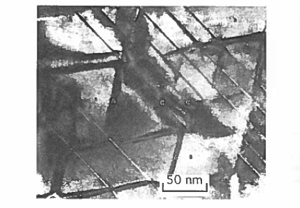
Figure 5.22. The microstructure of a \(\text{Sm}(\text{CoFeCuZr})_{7.8}\) magnet showing the cellular arrangement with 1:5 boundary layers which pin domain walls between the 2:17 grains (B). The coherent lamellae are (C). (Courtesy of G Hadjipanayis.)
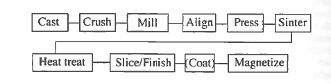
Figure 5.23. Process steps involved in producing rare - earth magnets by powder metallurgy.
Alternatively, it is possible to produce fine \(\text{SmCo}_{5}\) powder directly by reducing the rare - earth oxide powder with calcium. Possible reactions are \[2\text{Sm}_{2}\text{O}_{3}+20\text{Co}+3\text{CaH}_{2}\to4\text{SmCo}_{5}+3\text{CaO}+3\text{H}_{2}\text{O}\] \[ \text{Sm}_{2}\text{O}_{3}+10\text{CoO}+13\text{Ca}\to2\text{SmCo}_{5}+13\text{CaO}\] (5.2) These reactions are exothermic, being conducted at about 1100 °C in vacuum; they are known as the reduction - diffusion and the co - reduction processes, respectively. After calciothermic reaction, the lime and excess calcium are removed by washing, leaving an alloy powder which is suitable for further processing.
The next step is to align the crystallites of the powder in a magnetic field while pressing to obtain the green compact. Alignment and densification are
>Table 5.12. Properties of typical Sm - Co sintered magnets.
| \(\mu_{0}M_{\text{r}}\) (T) | \(H_{\text{c}}\) (kA m-1) | \((BH)_{\text{max}}\) (kJ m-3) | |
|---|---|---|---|
| 1:5 | 0.92 | 1500 | 160 |
| 2:17 high remanence | 1.20 | 1100 | 260 |
| 2:17 high coercivity | 1.07 | 1700 | 215 |
Typically the green compact has 65% of the bulk density.
The sintering conditions and heat treatment depend on the composition and microstructure required. The optimum composition is slightly Sm - rich. For \(\text{SmCo}_{5}\), a glance at the phase diagram (figure 5.16) shows that the phase is only stable above 805 °C. Normally the magnets are sintered at about 1150 °C and aged at 900 °C to eliminate inhomogeneities before quenching. A sintered \(\text{SmCo}_{5}\) magnet requires a reverse field which is a significant fraction of the anisotropy field before reversal occurs. Furthermore, nucleation of the magnetization reversal in a few crystallites in a small negative field does not propagate catastrophically through the magnet because the crystallites are magnetically decoupled at the grain boundaries.
The steps involved in making sintered \(\text{Sm(Co, Fe, Cu, Zr)}_{7 - 8}\) magnets are similar, except that a more complex series of heat treatments is needed to develop the cellular microstructure which leads to pinning - type coercivity. A typical composition is \(\text{Sm(Co}_{0.73}\text{Fe}_{0.20}\text{Cu}_{0.05}\text{Zr}_{0.02})_{7.7}\). The alloy is sintered at about 1180 - 1200 °C and then quenched to room temperature before ageing at 800 °C to precipitate the Zr - rich hexagonal phase and develop the coherent microstructures of the 2:17 matrix and 1:5 grain - boundary phases. A subsequent slow cool to 400 °C or annealing at 400 °C is required to develop coercivity.
The precipitation - hardened 2:17 material is quite suitable for making bonded magnets by compression or injection moulding as its coercivity is not compromised by further milling. Magnetization can present a problem, as large magnetizing fields, up to 5 T, may be needed for the high - coercivity precipitation - hardened material (the type (c) virgin curve in figure 5.20). Special magnetizing fixtures are designed for pulsed - field installations to impart the special pole patterns of magnetization, for example for a multipole rotor in a stepper motor.
Neodymium-Iron-Boron Magnets: The Powerhouse of Magnetism
The first two generations of rare - earth magnets were based on \(\text{Sm - Co}\). Difficulties with the world cobalt supply in the late 1970s, when its price exceeded that of Sm, made the development of an iron - based high - performance magnet an urgent priority. The \(\text{R}_{2}\text{Fe}_{17}\) compounds, for example, have low Curie points (figure 5.18) and easy - plane magnetic anisotropy. A ternary phase was required.
The new material discovered in 1983 in Japan by Sagawa (1984) at Sumitomo Special Metals and independently in the USA by Croat and Herbst at General Motors (Croat et al 1984) was a ternary phase stabilized by a small amount of interstitial boron (or carbon). Development of permanent magnets based on \(\text{Nd}_{2}\text{Fe}_{14}\text{B}\) was rapid because it was possible to adapt the techniques of powder metallurgy already in place for \(\text{Sm - Co}\) to make sintered magnets. A novel alternative processing route involving rapid quenching from the melt was also launched at GM to produce coercive nanostructured powder suitable for polymer bonding.
\(\text{Nd - Fe - B}\) magnets have here the highest energy product and the value of the annual production (\$1.5B in 1998) is over half that of ferrite (figure 1.12). In terms of cost per unit of magnetic energy, roughly \$5 per joule, the \(\text{Nd - Fe - B}\) is about five times as expensive. Despite the weak points of a rather low Curie temperature and susceptibility to corrosion, \(\text{Nd - Fe - B}\) magnets have found myriad uses, displacing \(\text{Sm - Co}\) in some cases and opening the way to a range of new products such as very thin voice - coil actuators needed for laptop computer disk drives. Properties and applications of \(\text{Nd - Fe - B}\) magnets are the subject of a book (Coey 1996) and several reviews (Buschow 1988, Herbst 1991).
The \(\text{Nd}_{2}\text{Fe}_{14}\text{B}\) compound has a tetragonal structure with space group \(P4_{2}/mm\) illustrated in figure 5.24. It can be considered as an alternation of planes containing neodymium in 4f and 4g sites, boron in 4g and iron in 4c sites, with double - puckered hexagonal sheets of iron, in 4e, 8j1, 16k1 and 16k2 sites. The last iron site \(8j_{2}\) is sandwiched between the hexagonal sheets. Moments on these sites differ widely, from \(1.9\ \mu_{\text{B}}\) for the 4c site which has four rare - earth neighbours, to \(2.8\ \mu_{\text{B}}\) for the \(8j_{2}\) site which is entirely surrounded by iron.
Intrinsic Magnetic Properties
Both the Nd and Fe sublattices are aligned parallel in \(\text{Nd}_{2}\text{Fe}_{14}\text{B}\) producing a room - temperature magnetization of 1.61 T, the largest of any rare - earth intermetallic that can be used for permanent magnets. Phases with the same structure exist for all rare earths, from Ce to Lu, but only \(\text{Pr}_{2}\text{Fe}_{14}\text{B}\) has a magnetization as high as \(\text{Nd}_{2}\text{Fe}_{14}\text{B}\). Compounds of the heavy rare earths have a ferrimagnetic structure (figure 2.1.1), but in no case does the moment of the rare - earth sublattices exceed that of the iron sublattices; no 2:14:1 compound shows a compensation point.
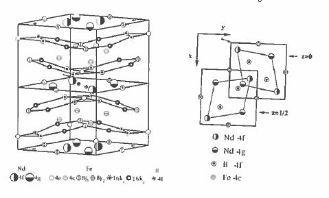
Figure 5.24. The crystal structure of \(\text{Nd}_{2}\text{Fe}_{14}\text{B}\). A view looking down the tetragonal axis is shown on the right.
As a result of the relatively weak Fe - Fe ferromagnetic exchange \(J_{\text{Fe - Fe}}k_{\text{B}}\approx39\ K\) in the approximately dense - packed structure, the Curie points of the \(\text{R}_{2}\text{Fe}_{14}\text{B}\) compounds are rather low; \(T_{\text{C}} = 585\ K\) for \(\text{Nd}_{2}\text{Fe}_{14}\text{B}\). Hence the R - Fe interaction can have some influence on \(T_{\text{C}}\) which is greatest when \(R = \text{Gd}\) (664 K, see figure 5.18). The interaction \(J_{\text{RF}}\) is plotted for different members of the series in figure 5.25. It is greatest at the beginning of the series on account of the greater 5d - 3d overlap, but it is almost constant for the heavy rare - earths. The Curie temperature varies as \(T_{\text{C}}=\frac{1}{2}(T_{\text{Fe - Fe}}+(T_{\text{Fe - Fe}}^{2}+4T_{\text{RF}}^{2})^{1/2})\) (1.230), where \(T_{\text{Fe - Fe}} = 566\ K\) and \(T_{\text{RF}}\) has the form predicted by de Gennes \[T_{\text{RF}} = 2n_{\text{RT}}\sqrt{\left(\frac{g_{\text{R}}}{g_{\text{R}}}-1\right)}C_{\text{R}}C_{\text{T}}\] (5.3)
Most of the anisotropy in \(\text{Nd}_{2}\text{Fe}_{14}\text{B}\) arises from the two Nd sites, which have \(mm\) point symmetry. Formally, a series of nine terms (3.34) \[ B_{0}^{2}\hat{O}_{2}^{0}+B_{2}^{2}\hat{O}_{2}^{2}+B_{4}^{2}\hat{O}_{4}^{0}+B_{4}^{2}\hat{O}_{4}^{2}+B_{4}^{4}\hat{O}_{4}^{4}+B_{6}^{0}\hat{O}_{6}^{0}+B_{6}^{2}\hat{O}_{6}^{2}+B_{6}^{4}\hat{O}_{6}^{4}+B_{6}^{6}\hat{O}_{6}^{6} \]
is needed to describe the crystal field interaction of the \(J = 9/2\text{Nd}^{3 +}\) ion at each site (compare section 3.1.3.4). In fact, it is adequate to consider just the leading term at room temperature, where \(A_{2}^{0}\) is about \(300\ Ka_{0}^{-2}\) at each site. Unlike the \(\text{Sm - Co}\) compounds of the previous section, where \(A_{2}^{0}\) is negative and no rare - earth substitution can enhance the anisotropy, there are heavy 4 Although Tm and Yb have larger values of \(\theta_{\text{s}}\), they are ineffective at increasing the anisotropy because of their weak exchange coupling to Fe.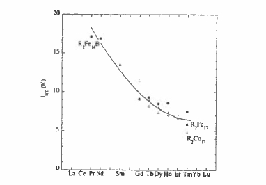
Figure 5.25. The R - Fe interactions for the 2:14:1 and 2:17 intermetallics.
rare earths (\(\text{Tb}\), \(\text{Dy}\)) with a negative quadrupole moment \(\theta_{2}\) (table 2.7) larger than that of Nd which can offer stronger anisotropy, albeit at the expense of reducing the magnetization on account of their antiparallel coupling with iron. The dysprosium compound, for example, has very large anisotropy and small quantities of Dy are often substituted for Nd to improve the coercivity of \(\text{Nd - Fe - B}\) magnets.
The fourfold symmetry axis is a \(4_{2}\) screw axis and the relation between equivalent 4f or 4g sites is seen in the plane view in figure 5.24. The macroscopic anisotropy must reflect the fourfold symmetry of the tetragonal structure, so the phenomenological anisotropy expression is
\(E_{u}/V = K_{1}\sin^{2}\theta+K_{2}\sin^{4}\theta + K_{2}'\sin^{4}\theta\sin4\phi+\cdots\). (5.4)
The sign of the \(K_{1R}=A_{2}^{0}\alpha_{J}\langle r^{2}\rangle\langle\hat{O}_{2}^{0}\rangle\) (section 3.2) is positive for Pr, Nd, Dy, Ho and Tb, but negative for Sm, Er, Tm and Yb for which the 4f quadrupole moment has the opposite sign (figure 2.21). The anisotropy contribution from the iron sublattice \(K_{1Fe}\) is positive, as seen from \(Y_{2}Fe_{14}B\) (table 5.12), where there is no magnetic rare – earth. The leading term in the total anisotropy energy is \(K_{1}=K_{1R}+K_{1Fe}\); the temperature dependence of the magnetization and anisotropy for \(Nd_{2}Fe_{14}B\) are shown in figure 5.28, together with \(K_{1R}\) and \(K_{1T}\). A rapid temperature dependence of the rare – earth moment may lead to a change of sign of \(K_{1}\) in compounds containing a rare earth with negative \(\alpha_{J}\) which produces a spin – reorientation transition at \(T_{sr}\) where \(M\parallel c\) for \(T > T_{sr}\) and \(M\perp c\) for \(T < T_{sr}\). The spin reorientations for \(Er_{2}Fe_{14}B\) and \(Tm_{2}Fe_{14}B\) are at 328 and 314 K, respectively.
A different sort of transformation of the spin structure may occur when \(K_{1}\) and \(K_{2}\) are of opposite sign, with a different temperature dependence.
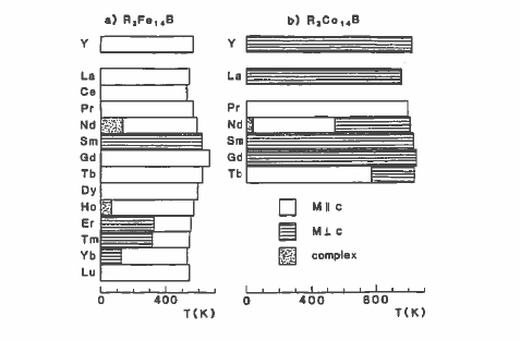
Figure 5.26. Magnetic structure and spin reorientations in \(\text{R}_{2}\text{Fe}_{14}\text{B}\) and \(\text{R}_{2}\text{Co}_{14}\text{B}\).
(see section 3.2.3). At low temperatures the higher - order terms in the crystal - field interaction vary as a high power of the sublattice magnetization (section 3.1.5.2) and, if \(K_{2}\) is negative, a structure where the net magnetization is tilted at an angle to \(c\) becomes stable. In \(Nd_{2}Fe_{14}B\) the tilt angle reaches \(30^{\circ}\) at \(T = 0\) and the spin - tilt transition begins at \(T_{st}=135\ K\). A similar transition occurs in \(Ho_{2}Fe_{14}B\) at \(T_{st}=57\ K\). No such transition occurs in \(Pr_{2}Fe_{14}B\), for example, because \(K_{2}\) is mainly governed by the term proportional to \(\theta_{4}A_{4}^{0}\langle\hat{O}_{4}^{0}\rangle\) and \(\theta_{4}(\beta_{4})\) is positive for Pr, but negative for Nd and Ho. It is impossible to use \(Nd_{2}Fe_{14}B\) magnets below 135 K because the coercivity disappears at \(T_{st}\) and permanent magnetism is destroyed. However, \(Pr_{2}Fe_{14}B\) may be used to the lowest temperatures.
Analogous transitions occur in the cobalt compounds, where \(K_{1\text{T}}\) is negative. Here, the compounds with positive \(\alpha_{J}\) exhibit spin reorientations; in \(\text{Nd}_{2}\text{Co}_{14}\text{B}\), for example, \(T_{\text{sr}} = 545\ K\) and \(T_{\text{st}} = 37\ K\). A summary of the magnetic structures and spin reorientations in 2:14:1 compounds is given in figure 5.26.
The most extensive information about the anisotropy constants \(K_{i}\) and the underlying crystal - field parameters \(A_{n}^{m}\) is obtained by fitting the magnetization curves of single crystals measured in high fields along the principal crystallographic directions. The rare - earth iron exchange constant \(J_{\text{RE - Fe}}\) is also a critical parameter for determining the shape of these curves. They may exhibit first - order magnetization processes (FOMPs), where the magnetization in a particular direction increases sharply as a critical field is exceeded (figure 5.27).
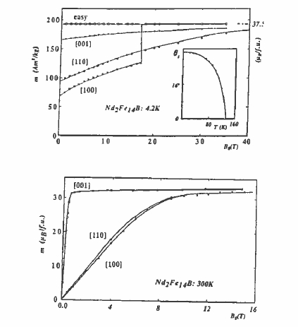
Figure 5.27. High - field magnetization curves of \(\text{Nd}_{2}\text{Fe}_{14}\text{B}\) at 4.2 K and at 300 K. The magnetization lies along 001, the \(c\) - axis, at 300 K, but it lies along no principal direction at 4.2 K.
The problem of determining a complete set of crystal - field parameters for \(\text{Nd}_{2}\text{Fe}_{14}\text{B}\) is complicated by the large number of parameters involved. Even data as extensive as those in figure 5.27 are insufficient to specify all of them. The ambiguity can be reduced by requiring that consistent sets of \(A_{n}^{m}\) be obtained for isostructural compounds of different rare earths.
The intrinsic magnetic properties of a set of compounds with the \(\text{Nd}_{2}\text{Fe}_{14}\text{B}\) structure are given in table 5.13. Isostructural cobalt compounds exist for rare earths from Pr to Tb. These compounds have Curie temperatures of about 1000 K.
The temperature dependences of the magnetization and anisotropy field, with the individual contributions to \(K_{1}\) from the Nd and Fe sublattices, are illustrated in figure 5.28.
When attempting to optimize the magnetic properties of \(\text{Nd}_{2}\text{Fe}_{14}\text{B}\) for a specific purpose, numerous possibilities for substitutions for the three constituent
Figure 5.27. High - field magnetization curves of \(\text{Nd}_{2}\text{Fe}_{14}\text{B}\) at 4.2 K and at 300 K. The magnetization lies along 001, the \(c\) - axis, at 300 K, but it lies along no principal direction at 4.2 K.The problem of determining a complete set of crystal - field parameters for \(\text{Nd}_{2}\text{Fe}_{14}\text{B}\) is complicated by the large number of parameters involved. Even data as extensive as those in figure 5.27 are insufficient to specify all of them. The ambiguity can be reduced by requiring that consistent sets of \(A_{n}^{m}\) be obtained for isostructural compounds of different rare earths.
The intrinsic magnetic properties of a set of compounds with the \(\text{Nd}_{2}\text{Fe}_{14}\text{B}\) structure are given in table 5.13. Isostructural cobalt compounds exist for rare earths from Pr to Tb. These compounds have Curie temperatures of about 1000 K.
The temperature dependences of the magnetization and anisotropy field, with the individual contributions to \(K_{1}\) from the Nd and Fe sublattices, are illustrated in figure 5.28.
When attempting to optimize the magnetic properties of \(\text{Nd}_{2}\text{Fe}_{14}\text{B}\) for a specific purpose, numerous possibilities for substitutions for the three constituent
Table 5.13Intrinsic magnetic properties of \(\text{Nd}_{2}\text{Fe}_{14}\text{B}\) - type compounds at room temperature.
| a (pm) | c (pm) | TC (K) | μ0Ms (T) | K1 (MJ m-3) | κ | μ0H0 (T) | \(\langle A_{2}^{0}\rangle\) (K \(a_{0}^{-2}\)) | |
|---|---|---|---|---|---|---|---|---|
| Y2Fe14B | 876 | 1203 | 566 | 1.44 | 1.1 | 0.8 | 2.0 | — |
| Pr2Fe14B | 880 | 1223 | 565 | 1.55 | 5.0 | 1.5 | 8.0 | 178 |
| Nd2Fe14B | 879 | 1218 | 585 | 1.61 | 4.9 | 1.5 | 7.6 | 300 |
| Sm2Fe14B | 879 | 1211 | 621 | 1.51 | -12.0 | — | 12.5 | 300 |
| Dy2Fe14B | 856 | 1199 | 598 | 0.72 | 12.5 | 5.5 | 27.8 | 295 |
| Nd2Fe13C | 881 | 1205 | 545 | 1.52 | 4.5 | 1.6 | 7.4 | 250 |
| Y2Co14B | 860 | 1171 | 1015 | 1.00 | -1.4 | — | (3.5) | — |
| Nd2Co14B | 863 | 1185 | 1007 | 1.06 | 2.2 | 1.6 | 5.2 | — |
elements can be exploited. Unfortunately, no single substitution simultaneously improves the three key properties of magnetization, Curie temperature and anisotropy. Cobalt substitution increases \(T_{\text{C}}\) and small quantities (\(<5\%\)) slightly increase the magnetization at room temperature, but cobalt decreases the anisotropy since the cobalt sublattice is easy - plane, opposite to that of iron (compare the values of \(K_{1}\) for \(\text{Y}_{2}\text{Fe}_{14}\text{B}\) and \(\text{Y}_{2}\text{Co}_{14}\text{B}\) in table 5.13). Dysprosium greatly increases \(K_{1}\) and slightly increases \(T_{\text{C}}\) but it rapidly reduces the magnetization. Since \(\text{Dy}_{2}\text{Fe}_{14}\text{B}\) is ferrimagnetic, \(H_{0}\) cannot be inferred directly from the perpendicular magnetization curve. Many high - grade \(\text{Nd - Fe - B}\) magnets contain both Co and Dy.
Isostructural series also exist where carbon replaces boron. These ternary carbides have slightly inferior properties to their boride counterparts.
Microstructure and Coercivity of \(\text{Nd - Fe - B}\) Magnets
The coercivity in \(\text{Nd - Fe - B}\) is discussed by Givord and Rossignol (1996). The coercivity mechanism in sintered magnets is similar to that in \(\text{SmCo}_{5}\) or \(\text{BaFe}_{12}\text{O}_{19}\). Sintered magnets are composed of oriented grains of \(\text{Nd}_{2}\text{Fe}_{14}\text{B}\) several micrometres in size (figure 5.29) which are multidomain in the unmagnetized state (figure 4.19).
Some micromagnetic parameters for the main types of permanent magnet are collected in table 5.18, where it is seen that the critical single - domain radius for \(\text{Nd}_{2}\text{Fe}_{14}\text{B}\) is \(R_{\text{sd}} = 0.12\ \mu\text{m}\), whereas the domain - wall width is \(\delta_{\text{B}} = 4.2\ \text{nm}\). The walls move freely across the crystallites in an applied field as the virgin sample is magnetized to saturation, as in figure 5.20(a). The coercivity depends on the ability of the magnet to resist nucleation and growth of reverse domains in a reversed magnetic field. This is more difficult to achieve in \(\text{Nd}_{2}\text{Fe}_{14}\text{B}\) than in \(\text{SmCo}_{5}\) because the anisotropy field is five times smaller.
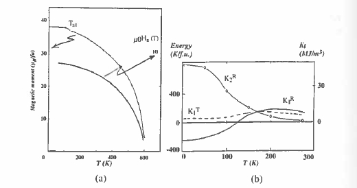
Figure 5.28. (a) The temperature dependences of the magnetization and anisotropy field for \(\text{Nd}_{2}\text{Fe}_{14}\text{B}\). (b) The contributions to \(K_{1}\) of the Fe and Nd sublattices.Figure 5.28. (a) The temperature dependences of the magnetization and anisotropy field for \(\text{Nd}_{2}\text{Fe}_{14}\text{B}\). (b) The contributions to \(K_{1}\) of the Fe and Nd sublattices.
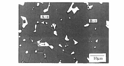
Figure 5.29. The microstructure of an \(\text{Nd - Fe - B}\) sintered magnet. A indicates the grains of \(\text{Nd}_{2}\text{Fe}_{14}\text{B}\), B is Nd - rich intergranular phase, C is \(\text{NdFe}_{2}\text{B}_{4}\). (Courtesy of I R Harris.)
Luckily the ternary \(\text{Nd - Fe - B}\) phase diagram is suitable for realizing a coercive microstructure (Knoch 1996). Microstructure and domain structure in \(\text{Nd - Fe - B}\) alloys have been discussed by Hadjipanayis (1996). Originally, the optimum composition for sintered magnets was found to be \(\text{Nd}_{15}\text{Fe}_{77}\text{B}_{8}\), which is both Nd - and B - rich with respect to the stoichiometric \(\text{Nd}_{12}\text{Fe}_{82}\text{B}_{6}\) composition. This falls in a region where three phases coexist at \(1050^{\circ}\text{C}\), \(\text{Nd}_{2}\text{Fe}_{14}\text{B}\), \(\text{NdFe}_{2}\text{B}_{4}\) and an Nd - rich liquid. The latter are both non - magnetic phases and the Nd - rich liquid promotes liquid - phase sintering where the \(\text{Nd}_{2}\text{Fe}_{14}\text{B}\) grains are wetted by a surrounding liquid film (figure 5.29). The surfaces of the hard - magnetic grains
are smooth and intergrain interactions are negligible, so the microstructure tends to prevent nucleation of reversed domains and the propagation of reversal from grain to grain. By contrast, an iron - rich composition would include micron - sized grains of \(\alpha\) - Fe in the microstructure which act as nucleation centres and prevent the development of coercivity. The ideal two - phase microstructure in an \(\text{Nd - Fe - B}\) sintered magnet consists of fully aligned grains of \(\text{Nd}_{2}\text{Fe}_{14}\text{B}\) separated by a minimum amount of a non - magnetic intergranular phase. The best commercial magnets approach this ideal.
A complete range of commercial grades of \(\text{Nd - Fe - B}\) magnet exists, some including substitutions of Dy or Co to improve the anisotropy or magnetization, and additives such as V, Mo or Zr to refine the microstructure. A typical composition of a high - coercivity grade is \(\text{Nd}_{13.5}\text{Dy}_{1.5}\text{Fe}_{76}\text{Nb}_{8}\), whereas a high - remanence grade may have composition \(\text{Nd}_{15}\text{Fe}_{77}\text{B}_{8}\), encased in
A different microstructure and magnetization process is encountered in nanocrystalline \(\text{Nd - Fe - B}\) magnets produced by melt - spinning or hydrogen processing. These processes usually yield material composed of tiny crystallites with an isotropic distribution of \(c\) - axis orientation, although some methods exist for texturing the material to make it anisotropic so that the easy axes become partly aligned. The crystallite size is of the order of \(2R_{\text{sd}}\) in these materials, and this is manifest in the virgin magnetization curve, which resembles that in figure 5.20(c). The initial magnetization process is relatively difficult as the domain walls tend to be trapped at the boundaries between the crystallites. The remanent state is composed of multi - domain domains composed of groups of crystallites where the \(c\) - axis lies in roughly the same direction (figure 4.21). Magnetization reversal is rather extended in the field, proceeding by nucleation and growth of reverse domains as in sintered magnets. The pseudodomains with the greatest misorientation to the applied field tend to be the last to saturate.
The drawback of isotropic magnets has already been emphasized in table 5.7 and figure 5.10; the maximum possible energy product is only a quarter of that of their fully oriented counterparts.
Fitting the phenomenological expression for discussed in section 3.3.2, \[H_{\text{c}}=\alpha_{\text{Kr}}H_{0}-D_{\text{eff}}M_{\text{s}}\] (5.5) to data on sintered \(\text{Nd - Fe - B}\) magnets yields \(\alpha_{\text{Kr}}\approx0.4\) and \(D_{\text{eff}}\approx1\), whereas data on melt - spun \(\text{Nd - Fe - B}\) magnets yield \(\alpha_{\text{Kr}}\approx0.8\) and \(D_{\text{eff}}\approx0.8\). The reduction in \(D_{\text{eff}}\) may be ascribed to the more granular crystallite phases in the melt - spun material.
A microscopic model for the coercivity in nucleation - type magnets relates the process to magnetization reversal in a critical volume. This activation volume can be deduced from an analysis of the magnetic viscosity (section 3.4). In \(\text{Pr - Fe - B}\) magnets, where this analysis can be conducted down to low temperatures, the activation volume is found to be a small multiple of \(\delta_{\text{B}}^{3}\).
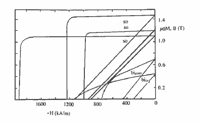
Figure 5.30. Demagnetizing curves of some grades of sintered oriented and bonded isotropic (compression or injection moulded) \(\text{Nd}_{2}\text{Fe}_{14}\text{B}\) magnets. (Courtesy of W Rodewald, Vacuumschmelze.)
\(\text{Nd - Fe - B}\) Magnet Processing
There are more ways of processing \(\text{Nd - Fe - B}\) than any other hard - magnetic material (Harris 1996). These may be divided into two main groups, the microcrystalline powder routes used to make sintered magnets and the nanocrystalline routes used mostly for bonded magnets.
The first group are variants of the process outlined in figure 5.23. The starting point is often an ingot produced by strip casting or batch induction melting of neodymium, iron and a ferroboron master alloy. The ingot is crushed and jet - milled under nitrogen to a fine powder, typically about 4 \(\mu\text{m}\) in size, often with the aid of hydrogen decrepitation. The powder is oriented in a magnetic field of about 1 T, pressed into blocks of green compact and then sintered in a vacuum furnace. A two - step treatment is then used for the \(\text{Nd}_{15}\text{Fe}_{77}\text{B}_{8}\) alloy, a sintering step at about 1080 °C for about 1 h to develop a dense three - phase material by liquid - phase sintering, followed by a soak for 1 - 2 h at about 600 °C to establish the coercivity. The microstructure is illustrated in figure 5.29.
Variants of the process have started with powder produced by reduction diffusion or co - reduction of the oxides with calcium: \[ \text{Nd}_{2}\text{O}_{3}+11\text{Fe}+\text{Fe}_{3}\text{B}+3\text{Ca}\to\text{Nd}_{2}\text{Fe}_{14}\text{B}+3\text{CaO}\] (5.6) \[2\text{Nd}_{2}\text{O}_{3}+11\text{Fe}_{2}\text{O}_{3}+2\text{Fe}_{3}\text{B}+39\text{Ca}\to2\text{Nd}_{2}\text{Fe}_{14}\text{B}+39\text{CaO}\] Polycrystalline coercive powder can also be produced by spray atomization from the melt. Another approach is the two - powder route where near - stoichiometric \(\text{Nd}_{12}\text{Fe}_{82}\text{B}_{6}\) powder is mixed with about 10% of Nd - rich powder to achieve liquid - phase sintering and grain isolation in a two - phase
Table 5.14. Properties of typical \(\text{Nd - Fe - B}\) magnets.
| \(\mu_{0}M_{\text{r}}\) (T) | \(H_{\text{c}}\) (kA m-1) | \((BH)_{\text{max}}\) (kJ m-3) | ||
|---|---|---|---|---|
| Standard | Oriented | 1.20 | 1000 | 260 |
| High remanence | Oriented | 1.46 | 1250 | 400 |
| High coercivity | Oriented | 1.15 | 2000 | 250 |
| Compression moulded | Isotropic | 0.70 | 800 | 76 |
| Injection moulded | Isotropic | 0.60 | 600 | 55 |
microstructure containing a minimum amount of the non - magnetic secondary phase.
Sintered \(\text{Nd - Fe - B}\) magnets are sold as Neomax and other names. Typical sintered blocks are 25 mm × 25 mm × 50 mm, with the magnetization direction along the short axis. They are sliced and ground or cut by spark erosion into desired shapes, coated with an anticorrosion layer such as nickel and then magnetized in a field of the order of 2 T. Other shapes such as radially oriented segments have been produced by hot extrusion of as - cast ingot material or compact isotropic powder. Sintering is the best way of making fully dense \(\text{Nd - Fe - B}\) magnets; grades with a high remanence tend to have less coercivity and vice versa. A standard grade typically has a remanence of 1.2 T and an energy product of 250 kJ m-3, while remanence in a premium grade approaches 1.5 T and the energy product reaches 400 kJ m-3 (table 5.14). Typical demagnetizing curves are shown in figure 5.30.
The melt - spinning process (figure 5.31) is the best example of the second group. A typical composition is \(\text{Nd}_{14}\text{Fe}_{80}\text{B}_{6}\). Melt - spinning involves ejecting a jet of molten alloy under inert atmosphere into a rapidly rotating copper wheel, where it solidifies at a rate of the order of \(10^{6}\ K\ s^{-1}\). The capacity of a large industrial machine is about 100 kg h-1. It is possible to obtain coercive ribbon, or flakes directly from the wheel by careful control of the process parameters, but it is more common to overquench to obtain the alloy in an amorphous state and then produce the required nanostructure in a subsequent annealing step. Flakes of melt - spun material, known by the trade name Magnequench (MQ), are typically 50 \(\mu\text{m}\) thick and 500 \(\mu\text{m}\) wide. The flakes are suitable for bonding with polymer to make isotropic magnets by compression or injection moulding (figure 5.11). Alternatively, they may be hot pressed to near full density to yield a dense isotropic magnet. If the material is extruded or allowed to flow perpendicular to the press direction (die - upset forging), a partly oriented dense magnet is achieved.
Energy products of 100 kJ m-3 and remanences of 0.80 T are characteristic of fully dense, isotropic \(\text{Nd - Fe - B}\). Typical energy products are 60 kJ m-3 for injection moulding and 80 kJ m-3 for compression moulding.
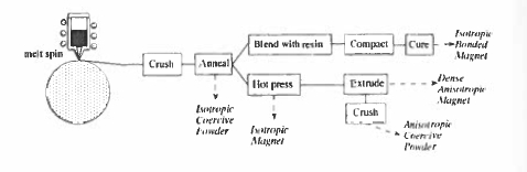
Figure 5.31. Process steps involved in making Nd-Fe-B magnets by melt-spinning.
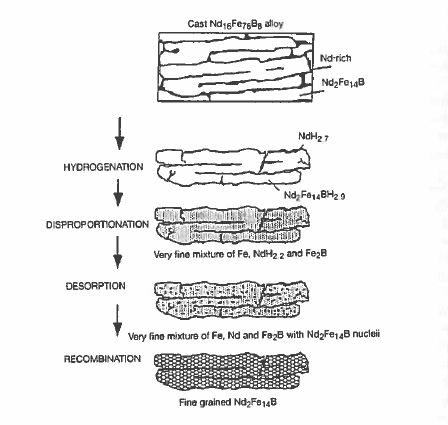
Figure 5.32. The hydrogcn-disproportionation-desorption-recombination process. (Hams 1996).
Similar coercive powders can be produced by high - energy ball milling of an alloy ingot or by rapid solidification followed by annealing to produce the necessary microstructure. The mechanically alloyed powder can then be processed in one of the same ways as the rapidly - quenched flakes.
The hydrogenation - disproportionation - desorption - recombination (HDDR) process is a method of refining the grain structure of a cast alloy or coarse powder to make it coercive. The process is illustrated in figure 5.32. Basically, it involves heating \(\text{Nd}_{2}\text{Fe}_{14}\text{B}\) in hydrogen up to the point where the disproportionation begins (equation 5.7). \[ \text{Nd}_{2}\text{Fe}_{14}\text{B}+2H_{2}\to2\text{NdH}_{2}+14\text{Fe}+\frac{1}{2}\text{B}_{2}\] (5.7) The hydrogen is then removed from the NH2 by pumping a vacuum, and the finely divided mixture of Nd, Fe and B is re - crystallized into nanosized \(\text{Nd}_{2}\text{Fe}_{14}\text{B}\) grains (equation 5.8 and 5.9).
Small additions of 0.1 wt% Zr have the dramatic effect of generating a textured array of submicron - sized crystallites which tend to have their c - axes aligned perpendicular to the plane of the ribbon in the original coarse powder from which they came. In this way an anisotropic powder is produced suitable for bonding. Energy products of 150 kJ m-3 are significantly greater than for isotropic bonded magnets and thus translated, for example, into a saving of weight or increase of torque in small electrical machines.
Neodymium-Iron-Boron Magnets: The Powerhouse of Magnetism
\(\text{Sm - Fe - N}\) and related intermetallic compounds
An elegant way of modifying the magnetic properties of iron - rich rare - earth intermetallics is to introduce small interstitial atoms into their structure as shown in figure 5.33 (Skomski 1996). Besides hydrogen, boron, carbon and nitrogen are small enough to enter the structure in this way, and these atoms have a profound effect on the magnetic properties. The rare - earth and iron atoms. There is in general some equilibrium solubility of the interstitial atoms. For example, in \(\text{Sm - Fe}\) there are three 2e octahedral interstitial sites per formula unit of \(\text{SmFe}_{12}\) and the \(\text{Zr}\) structure (figure 5.17) which may be occupied by nitrogen or carbon. The reactions \[ \text{Sm - Fe - p}+\frac{3}{2}\text{N}_{2}\to\text{Sm - Fe}_{12}\text{N}_{3}\] (5.8) is exothermic, with \(\Delta H\approx31\ kJ\ 181\ kJ\ mol^{-1}\), so the nitride is stable compared to the reactants (figure 5.34). However, the disproportionation reaction \[ \text{Sm - Fe - N}\to\text{SmN}+\text{Fe}+\frac{1}{3}\text{N}_{2}\] (5.9) is also exothermic with \(H\approx - 420\ kJ\ mol^{-1}\), so the nitride will tend to decompose unless it is impeded from doing so. The critical quantity here is the diffusion length for iron, \(\sqrt{Dt}\), which most significantly exceeds the inter - particle spacing only for very small particles. The decomposition can be thermally activated, \(D = D_{0}\exp(-E_{\text{a}}/kT)\). Figure 5.34 compares the diffusion length as a function of temperature after a fixed time for the diffusion of hydrogen, nitrogen and iron in \(\text{Sm - Fe - N}\). The figure shows that it is just possible to produce the nitride by a gas - solid reaction of nitrogen with fine
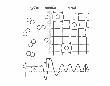
Figure 5.33. The gas - phase interstitial modification process. Molecular nitrogen is split at the surface and it diffuses in the bulk with an activation energy \(E_{\text{act}}\).
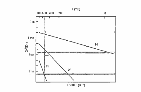
Figure 5.34. Diffusion of hydrogen, nitrogen and iron in \(\text{Sm}_{2}\text{Fe}_{17}\) as a function of temperature (Coey 1996). The maximum temperature for nitrogenation is shown by the dotted line.
\(\text{Sm}_{2}\text{Fe}_{17}\) powder. There is a window at about 400 °C where nitrogen can diffuse sufficiently to infiltrate the structure of a powder with grain size of the order of 1 \(\mu\text{m}\), without any appreciable diffusion of the iron. This gas - phase interstitial modification process is much easier for hydrogen than nitrogen: hydrogen can infiltrate a 1 \(\mu\text{m}\) grain in about 1 h at room temperature.
The effect of interstitial atoms on the intrinsic magnetic properties of iron - based intermetallics is quite remarkable (table 5.15). The Curie temperature
Table 5.15. Intrinsic magnetic properties of \(\text{R}_{2}\text{Fe}_{17}\) interstitial alloys at room temperature.
| a (nm) | c (nm) | TC (K) | μ0Ms (T) | K1 (MJ m-3) | μ0H0 (T) | \(A_{2}^{0}\) (K \(a_{0}^{-2}\)) | κ | |
|---|---|---|---|---|---|---|---|---|
| Y2Fe17 | 848 | 826 | 327 | 0.60 | -0.4 | — | — | — |
| Y2Fe17N3 | 865 | 844 | 694 | 1.46 | -1.1 | — | — | — |
| Y2Fe17C3 | 866 | 840 | 660 | 1.24 | -0.3 | 30 | — | — |
| Sm2Fe17 | 854 | 1243 | 389 | 1.00 | -0.8 | — | — | — |
| Sm2Fe17N3 | 873 | 1264 | 749 | 1.54 | 8.6 | 14 | -240 | 2.1 |
| Sm2Fe17C3 | 875 | 1257 | 668 | 1.43 | 7.4 | 13 | -200 | 2.1 |
of the 2:17 compound increases by as much as 400 °C after nitrogen loading; the influence of carbon or hydrogen is somewhat less. The Curie temperature increase is associated with an increase of lattice volume provoked by the interstitial atoms. This is 6% in \(\text{Sm}_{2}\text{Fe}_{17}\text{N}_{3}\), for example. The volume derivative \(d(\ln T_{\text{C}})/d(\ln V)\) is about 15 - 20. A similar value is obtained from the decrease of Curie temperature under pressure. There is a small increase of the zero - temperature saturation magnetization \(M_{0}\) of the iron sublattice associated with charge transfer to the interstitial atoms, but the main influence on the spontaneous room - temperature magnetization \(M_{s}\) is the enhanced Curie temperature.
From the point of view of permanent magnetism, the other important effect of interstitials is the effect they have on the crystal field at the neighbouring rare - earth sites. In the 2:17 structure, the three interstitials form an equilateral triangle around the rare - earth, creating a negative cubic field gradient \(A_{2}^{0}\approx - 240\ Ka_{0}^{-2}\), comparable to that in \(\text{SmCo}_{5}\). Samarium is the only light rare earth to exhibit uniaxial anisotropy in such a site and the permanent magnets formed from interstitial 2:17 - structure iron nitrides and carbides are all Sm - based.
The equilibrium concentration \(\langle c\rangle\) of nitrogen on the 9e sites as a function of pressure \(p\) is \[\langle c\rangle=\frac{1}{1+\sqrt{\left(\frac{p}{p_{0}}\right)}\exp(U_{0}/kT)}\] (5.10) where \(p_{0}\) is a constant and \(U_{0}\) is the net reaction energy, as illustrated in figure 5.33. At low pressures, this gives the square - root pressure dependence known as Sievert's law. Since the constant \(p_{0}\) is approximately 100 kbar and the net reaction energy \(U_{0}=-57\ kJ\ mol^{-1}\) for \(\text{Sm}_{2}\text{Fe}_{17}\), the equilibrium concentration is close to unity at 1 bar and 400 °C.
There are a variety of processing routes for Nitromag, the common name for Sm - Fe - N magnets, summarized in figure 5.35. The coercive powder may
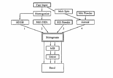
Figure 535. Gas processing routes for Sm-Fe-N magnets.
Table 5.16. Properties of \(\text{Sm - Fe - N}\) magnets.
| \(\mu_{0}M_{\text{r}}\) (T) | \(H_{\text{c}}\) (kA m-1) | \((BH)_{\text{max}}\) (kJ m-3) | ||
|---|---|---|---|---|
| Powder | 1.42 | 860 | 310 | |
| Compression moulded | Oriented | 0.96 | 630 | 175 |
| Compression moulded | Isotropic | 0.61 | 800 | 65 |
be produced by fine milling a \(\text{Sm}_{2}\text{Fe}_{17}\text{N}_{3}\) powder produced by nitrogenating an \(\text{Sm}_{2}\text{Fe}_{17}\) powder produced from an ingot or by a reduction - diffusion process. Otherwise, nanocrystalline \(\text{Sm}_{2}\text{Fe}_{17}\) may be prepared by HDDR, mechanical alloying or melt - spinning. Powder made by the former routes may be monocrystalline and therefore orientable in a magnetic field. That made by the latter routes is inevitably polycrystalline, as each powder particle contains hundreds or thousands of nanocrystallites. The nanocrystalline powder is typically very fine (about 2 \(\mu\text{m}\)) and it is advantageous to coat it with a thin layer of zinc to improve its stability and loop shape. In any case, the nitrides are used to produce isotropic or anisotropic bonded magnets, but any high - temperature sintering or consolidation is precluded by the metastability of the phase. Some typical magnet properties are shown in table 5.16.
Similar phases made with interstitial carbon have better stability, but inferior intrinsic magnetic properties. They may be stabilized to quite high temperatures by substitutions such as Al or Ga for iron in the structure. It is possible to hot press \(\text{Sm}(\text{Fe}_{15}\text{Ga}_{2})\text{C}_{2}\), for example.
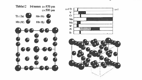
Figure 5.36. The crystal structure of \(\text{ThMn}_{12}\). The dashed lines show the relation to the \(\text{SmCo}_{5}\) - type cell. Stability ranges for the iron - rich compounds are indicated in the top - right hand panel.
\(\text{ThMn}_{12}\) - Structure Compounds
\(\text{ThMn}_{12}\) has a tetragonal structure (space group \(I4/mmm\)) with the large Th atoms in \(2a\) sites with \(4/mmm\) symmetry and three different Mn sites. The structure is derived from that of \(\text{SmCo}_{5}\) by substituting \(\text{Co}_{2}\) dumbbells along half the Sm in such a way that the \(c\) - axis of the 1:12 cell lies along the \(a\) - axis of the 1:5 cell (figure 5.36).
The \(\text{ThMn}_{12}\) compounds form for most rare earths in place of Th, but these compounds are of no interest here because the manganese orders antiferromagnetically. There is no 1:12 compound in any of the \(\text{R - Fe}\) or \(\text{R - Co}\) binary phase diagrams, but the structure can be stabilized in pseudobinary compounds by small amounts of light transition metals. These compounds are ferromagnetic, with Curie temperatures of the order of 550 K (Li and Coey 1991). Polarization exceeds 1.0 T at the iron - rich end of the stability range.
Intrinsic magnetic properties of some representative compounds are given in table 5.17. \(A_{2}^{0}\) is small and negative, about \(- 30\ K\ a_{0}^{-2}\), but the anisotropy and magnetization of \(\text{Sm(Fe}_{11}\text{Ti})\) and \(\text{Sm(Fe}_{10}\text{V}_{2})\) are just adequate for permanent magnet applications. It is possible to produce isotropic coercive powder by melt - spinning or mechanical alloying.
The Curie temperature and anisotropy can be increased by interstitial modification with nitrogen or carbon, which occupy a pair of \(2b\) octahedral interstitial sites above and below the rare earth, producing a positive field gradient \(A_{2}^{0}\approx300\ K\ a_{0}^{-2}\). It follows that the Pr or Nd compounds with nitrogen or carbon are the candidates for permanent magnet development.
Table 5.17. Intrinsic magnetic properties of some \(\text{ThMn}_{12}\) - structure compounds at room temperature.
| a (pm) | c (pm) | TC (K) | μ0Ms (T) | K1 (MJ m-3) | μ0H0 (T) | κ | |
|---|---|---|---|---|---|---|---|
| Y(Fe11Ti) | 850 | 479 | 520 | 1.27 | 1.7 | 3.4 | 1.2 |
| Sm(Fe11Ti) | 856 | 480 | 584 | 1.14 | 4.8 | 10.5 | 2.1 |
| Y(Fe10.5V1.5) | 847 | 477 | 575 | 1.02 | 1.1 | 2.6 | 1.1 |
| Y(Fe10.5V1.5)N | 861 | 479 | 793 | 1.31 | 0.7 | 1.3 | 0.7 |
| Nd(Fe10.5V1.5)N | 862 | 481 | 784 | 1.34 | 5.5 | 10.2 | 2.0 |
Table 5.18. Micromagnetic parameters for permanent magnet compounds.
| A (pJ m-1) | Ms (MA m-1) | K1 (MJ m-3) | κ | Rsd (μm) | lex (nm) | δB (nm) | γ (mJ m-2) | |
|---|---|---|---|---|---|---|---|---|
| BaFe12O19 | 6 | 0.38 | 0.33 | 1.4 | 0.34 | 6.7 | 13.5 | 6 |
| MnAl(C) | 8 | 0.75 | 1.7 | 1.9 | 0.24 | 3.4 | 6.8 | 15 |
| CuPt | 10 | 1.00 | 4.9 | 2.5 | 0.25 | 2.8 | 4.5 | 28 |
| SmCo5 | 22 | 0.84 | 17.2 | 4.4 | 0.84 | 4.9 | 3.6 | 78 |
| Sm2Co17 | 25 | 1.03 | 3.3 | 1.6 | 0.25 | 4.3 | 8.6 | 36 |
| Nd2Fe14B | 8 | 1.28 | 4.9 | 1.5 | 0.12 | 1.9 | 3.9 | 25 |
| Sm2Fe17N3 | 12 | 1.22 | 8.6 | 2.1 | 0.19 | 2.5 | 3.6 | 40 |
A series of compounds exist with hybrid structures incorporating aspects of the 1:12 and 2:17 structures, with formulae such as \(\text{R}_{3}\text{T}_{29}\). Their symmetry is monoclinic and they may be interstitially modified in the same way as other compounds discussed in this section.
Table 5.18 summarizes the micromagnetic properties of the most significant materials discussed in this chapter.
New Approaches in Rare-Earth Magnet Design and Development
The search for pseudobinary and ternary rare - earth intermetallics suitable for permanent magnet applications conducted in the 1980s and 1990s came up with the compounds presented above and some others with closely related structures. New approaches are now being developed to improve magnetic properties or reduce the processing costs. These involve materials which are structured on the scale of the domain - wall width \(\delta_{\text{B}}=\pi\sqrt{A/K_{1}}\) or the exchange length \(l_{\text{ex}}=\sqrt{A/\mu_{0}M_{\text{s}}^{2}}\). These quantities are only a few nanometres in size (table 5.18), so we have to consider nanostructures, which may be of one of two types as illustrated in figure 5.37.
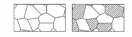
Figure 5.37. One- ami two-phase nanostructures. Each grain may be 20-30 nm in size.
One - Phase Nanostructures
A major drawback of the nanocrystalline coercive powder produced by melt - spinning or the HDDR process is that the orientation of the crystalline grains in a powder particle is essentially isotropic. In the absence of intergranular exchange coupling, this reduces the remanence to half the spontaneous magnetization and the maximum energy product which varies as \(M_{s}^{2}\) is reduced by a factor of four (section 3.3.4). The problem is similar to that of isotropic bonded magnets. A solution is to make a structure where adjacent crystallites are exchange - coupled across the grain boundary, so that within a distance \(\delta_{\text{B}}\) of the boundary the magnetization points in a direction intermediate between the easy axes of the two crystallites. The effect is to increase the remanence ratio, \(M_{r}/M_{s}>0.5\), at the expense of a reduction in coercivity (figure 3.38). The remanence enhancement is isotropic, so the nanostructured material can be magnetized in any desired direction; no orientation is necessary. The nanostructured materials may be produced by melt - spinning or mechanical alloying.
Two - Phase Nanostructures
The rare - earth intermetallics discussed here have anisotropy greatly in excess of that strictly required to produce the coercivity \(H_{\text{c}} = M_{\text{s}}/2\) required for a good permanent magnet. None of them has a magnetization as high as that of iron or \(\text{Fe}_{65}\text{Co}_{35}\). The idea of the two - phase nanostructures is to exchange - couple a rare - earth intermetallic hard phase to a soft phase so that the magnetization and anisotropy of the composite are some average of the two (Kneller and Hawig 1991). For this to be effective, the size of the soft grains should not exceed a small multiple of the wall width \(\delta_{\text{B}}\) for the hard phase, perhaps 20 nm (Skomski and Coey 1993). In this way, the hard grains serve to stiffen the magnetization of the whole material. These nanocomposites are also known as exchange - spring magnets because they exhibit a high recoil permeability in the second quadrant; in this quadrant the hard grains do not easily reverse and the magnetization of the soft phase is reversible. The principle is illustrated in figure 5.38. Practical two - phase nanostructures are based on \(\text{Nd}_{2}\text{Fe}_{14}\text{B}-\text{Fe}\), \(\text{Nd}_{2}\text{Fe}_{14}\text{B}-\text{Fe}_{3}\text{B}\), or \(\text{Sm}_{2}(\text{Fe},\text{Co})_{17}-(\text{Fe},\text{Co})\) or \(\text{Sm}_{2}\text{Fe}_{17}\text{N}_{3}-(\text{Fe},\text{Co})\) mixtures produced by melt - spinning, with additions to impede grain growth of the soft phase. They are
Figure 5.38 The principle of the two-phase nanostruclured exchange-spring magnet ( Knellerand Hawig 1991).
Figure 5.39. Remanence and coercivity of two - phase \(\text{Nd}_{2}\text{Fe}_{14}\text{B}-\alpha\text{-Fe}\) magnets. The formula is \(\text{Nd}_{x}\text{Fe}_{100 - x}\text{B}_{x/2}\).
isotropic, but offer remanence \(\mu_{0}M_{\text{r}}\approx1.0\ T\) and \(H_{\text{c}}\approx0.5\ MA\ m^{-1}\). There is the inevitable trade - off between remanence and coercivity which is illustrated in figure 5.39.
The ideal two - phase magnet is an aligned nanostructure with \(c\) - axis - oriented hard layers interspersed with thin soft layers and energy products of about 1 MJ m-3 may be expected in model systems (section 3.3.3.3). This is the ultimate energy product that can be expected for permanent magnets operating at room temperature.


