

4.11 Analysis on Lamella Phase of Grain Boundary in Micro - structure of NdFeB Permanent Magnetic Alloy
In recent years study on microstructure and coercivity of NdFeB alloy has achieved great progress, but for mechanisms of nucleation and pinning there still needs discussion. K. Hiraga, et al considered that there existed lamella phase of bcc in crystal interface surrounding \(Nd_{2}Fe_{14}B\) granule (Pan, Zhao, Ma, 1988). And some others considered that this bcc phase was formed in preparation process (Pan, Liu, Luo, 1990). In order to have a clearer understanding of microstructure around the grain interface, authors made systematically observation and analysis using HVM. This section is not to explain these phenomena but is to issue information obtained in experiments for further discussion.
Experimental method
Two permanent magnets of \(Nd_{16}Fe_{77}B_{7}\) and \(Nd_{16}Fe_{57}Co_{16}Ga_{4}B_{7}\) were prepared by
normal powder metallurgy method. The magnet was thinned by machine and ion to prepare samples for electronic microscope. Rising of temperature and oxidation should be avoided by all efforts. The in situ and dynamic observation on prepared samples was conducted under JEM - 1000 HVM.
Magnetism measurement
Magnetic characteristic of sample of \(Nd_{16}Fe_{77}B_{7}\) was: \(B_{r}=1.22\ T\), \(H_{c}=824\ kA/m\), \((BH)_{max}=280\ kJ/m^{3}\); that of \(Nd_{16}Fe_{57}Co_{16}Ga_{4}B_{7}\) was: \(B_{r}=1.1\ T\), \(H_{c}=766.4\ kA/m\), \((BH)_{max}=214.8\ kJ/m^{3}\).
Analysis on result of the in situ and dynamic observation of samples
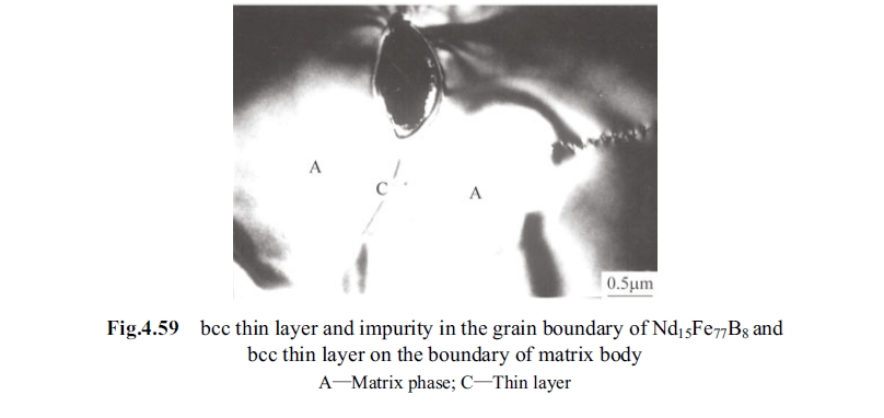
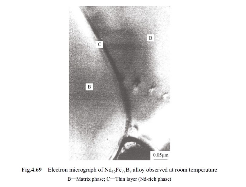
The matrix phase of \(Nd_{2}Fe_{14}B\), B - rich phase of \(Nd_{1 + \varepsilon}Fe_{4}B_{4}\) (\(\varepsilon = 0.1 - 0.3\)) and Nd - rich phase were observed under JEM - 1000 HVM. In addition a bcc lamella phase was found in crystal interface. The following is to analyze state of bcc lamella in the crystal interface and its order of change with temperature. Fig.4.59 is the microstructure around boundary of \(Nd_{2}Fe_{14}B\). Where A is the matrix phase, C is lamella in crystal interface; Fig. 4.60 is the other figure of the lamella texture in crystal interface, i.e., a clear lamella texture existed in crystal interface between two Nd - rich phases, and this type of lamella texture extended to interior of crystal granule in part of area. Author considered that this lamella belt might be formed in crystal interface and interfaces (there was lamellar texture between includes and the matrix phase, as shown in Fig.4.59), this type of filmy belt may extend to interior of the matrix phase of \(Nd_{2}Fe_{14}B\) if there are some other types of plane defects near crystal interface and connection locals of the interfaces. If the
filmy belt were formed by oxidation in preparation process it was difficult to extend to interior of the matrix phase evenly. Moreover, this filmy belt existed widely in samples and it was evenly in width. Therefore, author considered that this belt was impossible to form in preparation process, but it was inherent in magnet after annealing process.
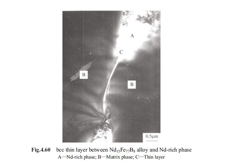
By analysis this filmy belt is Nd - rich phase with a thickness of 20nm, which appeared in crystal interface and cross corner after disappearance of Nd - rich phase by annealing at \(580 - 635^{\circ}C\); it belongs to fcc crystal structure with lattice constant \(0.56\ nm\); the content of neodymium in the lamellar belt is about 85%.
This lamellar Nd - rich phase acts important function for magnetic hardening of sintered NdFeB alloy. If Nd - rich phase is insufficient in the alloy the coercivity would be very low (though \(B_{r}\) is high) and the general magnetic performance would not be good.
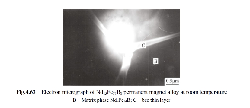
Fig.4.61 is the magnified photo of the filmy belt in Fig.4.60. The figure of the filmy belt can be seen more clearly that it is not an integral crystal but are many small interfaces existed which can be taken as microcrystal. Fig.4.62 is Nd - rich phase in intersectant locus of three filmy belts, equivalent to a trifurcate interface, and each interface is occupied by bcc lamella. As shown in Fig.4.63 that the included angle among three filmy belts is about \(120^{\circ}\). Among them two are linked with each other and the other one is independent, they are Nd - rich filmy belts between the matrix phases.
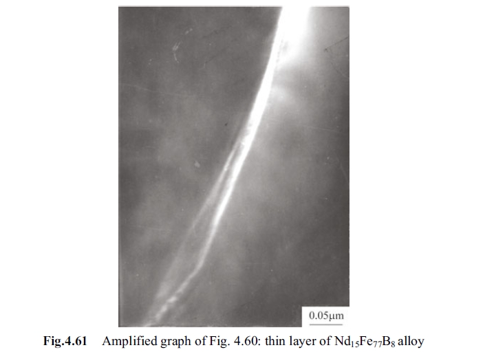
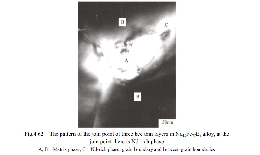
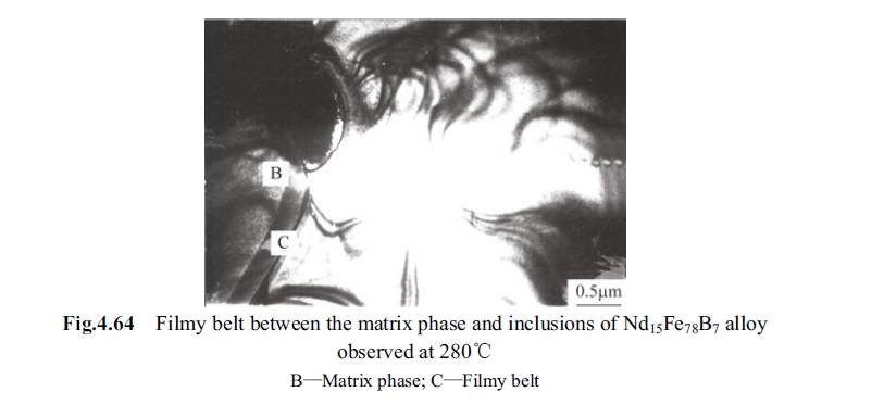
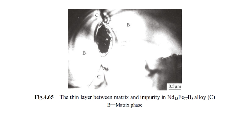
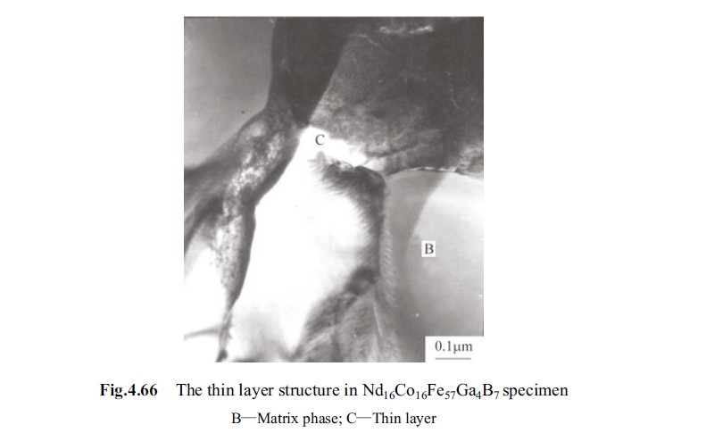
Fig. 4.64 is the lamellar phase in crystal interface observed \(280^{\circ}C\). Fig. 4.65 the filmy belt between includes and the matrix phase. There was uneven microstructure in the filmy belt. The filmy belt was also observed in sample of \(Nd_{16}Fe_{57}Co_{16}Ga_{4}B_{7}\), as shown in Fig. 4.66. The formation of filmy belt can prevent growth up of crystal granule, and crystal interface have big resistant for movement of the domain wall. In addition, the belts have low anisotropy thus they may act as effective pinning stand to improve coercivity of material.
What is showed in Fig. 4.62 belongs to grain boundary of multiple phases, the Nd - rich globules in crystal interface of multiple phases congregated to be larger Nd - rich conglomerations, and the larger ones existed in cross corner of three crystal granules of \(Nd_{2}Fe_{14}B\). When annealing at \(630^{\circ}C\) neodymium in Nd - rich conglomerations extended along crystal interface to the interface so that led to homogenization. The thickness of lamella of Nd - rich phase in the interface is different because of different technical system.
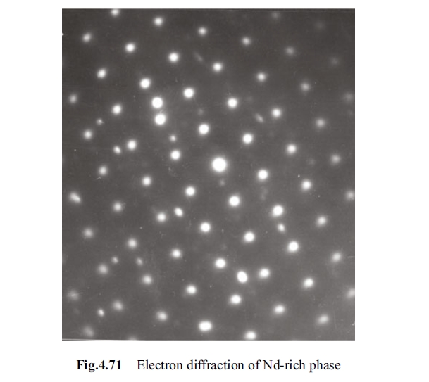
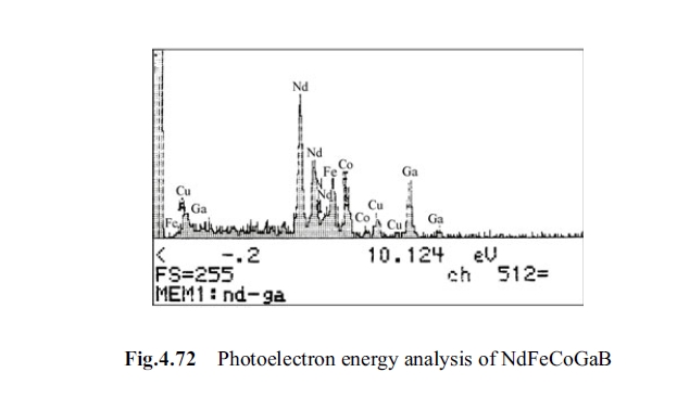
Fig. 4.60 shows magnified of ashine Nd - rich filmy belt. It can be seen that there are small granules in the belt. For formation of the filmy belt many articles have presented different opinions as per their experiments. Some thought that is the broken off of the Nd - rich phase in process preparing the filmy sample for electronic microscope, possibility of this opinion is not excluded because the sample for observation under transmission electronic microscope must be very thin. In the experiment JEM - 1000 HVM was used with super - high voltage for accelerating voltage, and thus with high transmission rate can observe comparatively thicker film. One of characteristics of HVM is to observe filmy sample with thickness below 100 nm. As shown in Fig. 4.67 to Fig. 4.70, Nd - rich filmy belt in the interface mention before has ascertain thickness and this ashine Nd - rich lamella was had extended in 5 times at \(312^{\circ}C\), its magnified photo is shown as in Fig. 4.70. It can be seen that there were Nd - rich tiny particles from several nm to more than ten nm. Samples with the same composition but with different aging program were designed in order to describe the contribution of Nd - rich filmy belt. The result revealed that the sample with such Nd - rich filmy belt in microstructure had higher coercivity in measurement. This type of Nd - rich filmy belt has fcc structure, its atom fraction is Nd 75%, and iron in balance. Its electronic diffraction photo is shown as in Fig. 4.71, and its photoelectron energy spectrum is as Fig. 4.72.


This type of lamella in crystal interface has almost disappeared in NdFeB alloy more than ternary system, as shown in Fig.4.66 for alloy of \(Nd_{16}Co_{16}Fe_{57}Ga_{4}B_{7}\). The Ga - rich phase (\(Ga_{2}Nd\), \(GaNd\), \(Ga_{3}Fe_{11}Nd_{6}\)) of this type in crystal interface of multi - phases congregated herein. In crystal interface of alloys exceeding ternary elements it is hard to find three ashine lamellas distributed in \(120^{\circ}\). Nd - rich lamella with thickness of 20 - 30 nm and fcc structure of lattice constant \(0.56\ nm\), which has contributes to coercivity of the alloy.
There are several types of Nd - rich phases. But compared with analysis of phase diagram Nd - rich phases can be taken as Nd - Fe binary eutectic alloy (Zhou, Dong1999)
Phase diagram indicates that the eutectic temperature of Nd - Fe binary al-loy is \(640^{\circ}C\), that of ternary alloy of NdFeB is \(655^{\circ}C\) and Nd - rich phase in cross corner of crystal interface became liquid phase at \(640^{\circ}C\). In experiment the edg-ing program technique, with important effect on coercivity of the alloy, was dif-ferent with different alloy composition, not all at \(600^{\circ}C\). Nd - rich crystal interface for NdFeB alloy with element more than three was not pure Nd - rich phase yet. To bring the multi - phases to be homogenized it needs to look at the combination ability of the adding element with iron. Determination of appropriate aging pro-gram needs to refer to phase diagram and a lot of experiments of different aging times and aging temperature.
When cooling sintered NdFeB alloy there was a deep eutectic tendency to keep the liquid out-of-order texture to room temperature because the eutectic tempera-ture of ternary NdFeB elements have big different with melting points of iron and neodymium. Neodymium presents Nd - rich phase with different forms, different uniformities and different types, as shown as single phase interface in Fig. 4.63 and Fig. 4.64, and multi - phases interface of multi - components in Fig. 4.66 be-cause of cooling velocity (quenching or cool with furnace) of sintered alloy. Owing to deep eutectic (out-of-order deep eutectic) Nd - phase in crystal interface goes deep into interior of \(Nd_{2}Fe_{14}B\), \(Nd_{2}(Fe, Co)_{14}B\), \(Nd_{2}(Fe, Nb)_{14}B\) and \(Nd_{2}(Fe, Ga)_{14}B\). To obtain clean Nd - rich phase and heighten coercivity doubly it needs multi - melting aging. This explains why the sintering program for NdFeB alloy will be two - stage aging, at \(900^{\circ}C\) and \(600^{\circ}C\), respectively, and some type of alloy does not need aging at \(900^{\circ}C\). Therefore, author found in experiment that some-times quadrate degree of demagnetization curve of one stage aging is better than that of two - stage aging. Generally, the more are the elements alternated in NdFeB alloy the more is the effort made to search for heat treatment program and melting program. To determine these programs repetitious experiments are necessary. Determination of heat treatment temperature is related to types and states of row materials, for example, to use dysprosium or Dy - Fe alloy, use boron or B - Fe alloy, use metallic niobium or Nb - Fe alloy. Binary alloy phase diagram needs to be utilized to melting, sintering and heat treatment programs. Un-der the correct programs Nd - rich phase can exert verily its function in assist sin-tering, alloy densification and heightening coercity.
The type and figure of Nd - rich phase are related to neodymium content in composition. To make the NdFeB alloy of high magnetic energy product just needs to act the mentioned functions really without excessive neodymium and heighten the proportion of magnetic phase of \(Nd_{2}Fe_{14}B\) as much as possible.
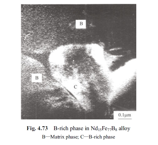
Neodymium in NdFeB alloy needs to supply B - rich phase besides supplying Nd in \(Nd_{2}Fe_{14}B\) and Nd in Nd - rich phase, that is, Nd in \(Nd(1 + \varepsilon)Fe_{4}B_{4}\) (\(\varepsilon = 0.1 - 0.3\)). The B - rich phase is nonmagnetic phase, which is hard to be observed ordinarily.
Its forms are different because there are not simple multiple relation between \(c_{Fe - x}\) and \(c_{Nd}\). It is the type of a one - dimension with incommensurate structure varying composition. This compound is similar to Nowotny phase such as \(MnSi_{2 - x}\), etc., and is a special crystalline structure, or being called chimney - ladder structure. It belongs to paramagnetic phase so that its study has been neglected by researchers working on magnetic materials. Experiments found that B - rich phase had lattice aberrance at \(322^{\circ}C\), and the layer dislocation in B - rich phase was stable from room temperature to \(500^{\circ}C\), but at that temperature precipitates (\(Nd_{2}O_{3}\)) appeared in \(Nd_{2}Fe_{14}B\) and Nd - rich phases. The B - rich phase is paramagnetic phase at room temperature; its Curie temperature is 13K but it still stable at \(500^{\circ}C\). The purpose to add boron is to form ferromagnetic phase of \(Nd_{2}Fe_{14}B\), excessive part is to form isolated B - rich phase, as shown in Fig. 4.73. B - rich phase can be pinning point on domain wall of reverse magnetization nucleus.
The structure of the deposits changed from amorphous structure to microcrystalline as the metal ion concentration ratio increased. When the metal ion concentration ratio was within 0.3 - 0.5, the cellular size of the deposit surface decreased gradually with the metal ion concentration ratio increase. When the metal ion concentration ratio increased up to 0.6, the cellular size of the deposit surface coarsened and presented a microcrystalline morphology, indicated that there was a critical value within 0.5 and 0.6, and when it was smaller than the value, the structure was amorphous, and cellular morphology was not obvious, but the deposit structure began to change from amorphous to microcrystalline morphology (Yuan, Cao, Feng, et al, 2010).


