

6.5 Other Applications of Magnetism: Emerging Technologies and Innovations
Superconducting Permanent Magnets: Revolutionizing Magnetic Systems
Superconducting magnets are usually understood to be electromagnets made from coils with numerous turns of superconducting wire. However, a solid block or ring of superconducting material may have some of the properties of a
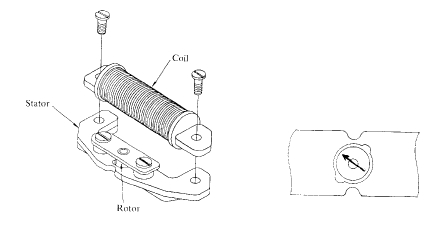
Figure 6.33. . A two - pole stepping motor used in clocks and watches. In watches the magnet made of bonded \(\text{Sm}_{2}\text{Co}_{17}\) has a mass of a few milligrammes.
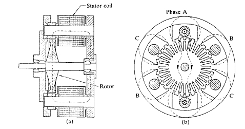
Figure 6.34.. A miniature hybrid stepping motor.
permanent magnet if it is cooled below its superconducting transition temperature \(T_{\text{c}}\) in a field so that it traps some flux. Blocks of melt - textured high - temperature superconductors are potentially useful. The supercurrents flowing at the surface of the material to maintain \(B\) are somewhat analogous to the perpetual electronic currents which flow to produce magnetic moments. The hysteresis loops of a type II superconductor are illustrated in figure 6.35. Large flux densities, 5 T or more, are achievable with superconducting permanent magnets, since they are limited only by the upper critical field. However, the superconductor does not possess the same ability to do reversible work as a permanent magnet
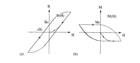
Figure 6.35.. The \(B:H\) and \(H:H\) loops of a type II superconductor.
because, unlike a permanent magnet, its magnetization is not independent of field. Another drawback is that the magnetization is nonuniform, with the average value of \(M\) in a block being only one - third of the maximum value at the centre. Large applied fields are necessary to charge the superconducting blocks.
Spin Electronics: The Future of Magnetism in Computing and Technology
Conventional electronics operate with no regard for the electron spin. However, the trend towards further miniaturization of electronic logic and memory elements has led to the consideration of schemes for electronics of the future where the electron spin plays a key role in the operation of the devices.
The simplest two - terminal magnetoelectronic device is a sensor that depends on anisotropic magnetoresistance. The resistance of 3d metals and alloys such as permalloy (\(\text{Fe}_{22}\text{Ni}_{78}\)) depends slightly on the relative orientations of the current and magnetization directions. The resistance is \(R_{0}+\Delta R\cos^{2}\theta\), where \(\theta\) is the angle in question and the magnitude of the effect \(|\Delta R/R|\) is about 2%. When used as a field sensor, the thin - film device of figure 6.36(a) has a linear response when \(\theta\approx45^{\circ}\). A bias field greater than the field to be sensed can be provided by an adjacent permanent - magnet layer. The bias field eliminates domains and leads to a single - domain sensor with no Barkhausen noise.
The spin - valve is a current - in - plane device composed of a sandwich or multilayer of alternate magnetic and non - magnetic metallic layers, typically Co and Cu. The coupling between the two ferromagnetic layers \(M_{1}\) and \(M_{2}\) in the sandwich of figure 6.36(b) is weak and each has a different switching field, which may be determined, for example, by shape anisotropy. The magnetization of one of the layers, \(M_{1}\), is then pinned by a bias field which can be produced, for example, by a thin permanent magnet or an adjacent, exchange - coupled antiferromagnetic layer.
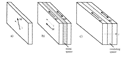
Figure 6.36.. Three types of spin - electronic devices where the resistance depends on the applied magnetic field. (a) A single - film ferromagnetic sensor depending on anisotropic magnetoresistance, (b) a spin valve, and (c) a magnetic tunnel junction. (b) and (c) may serve as sensors or memory elements.
This produces a shifted hysteresis loop and the free layer can then flip in a small external field, thereby changing the resistance of the device by about 10%.
The spin – polarized tunnel junction likewise depends on influencing the resistance by changing the relative orientation of the magnetization of two ferromagnetic layers (\(M_1\) and \(M_2\)). This is a current – perpendicular – to – plane device where a thin (about 5 nm) insulating barrier separates the two metallic electrodes. Changes of resistance ≥ 30% are achieved with Co, Fe – Co or permalloy electrodes. The tunnel junctions are used as sensors, but also as memory elements, where the direction of magnetization of the free layer encodes the binary information, which may be read out with sense lines in non – volatile magnetic random – access memory (MRAM).
More advanced, three – terminal devices have come into being that operate directly on the electron spin, using switches based on ferromagnetic metals which have different impedance in the \(\downarrow\) and \(\uparrow\) channels. These devices require permanently magnetized metals to act as spin – polarized electron injectors, as well as elements whose magnetization can be switched at will. Spin electronics may finally lead to the integration of magnetism in electronics at the chip level, a union already achieved with optics in various opto – electronic devices.


