
6.4 Dynamic Applications with Active Recoil: Advancing Motion Control
Magnetic Actuators: Precision Control in Modern Technology
An actuator is any electromechanical drive with a limited linear or angular displacement. This definition encompasses loudspeakers, microphones,
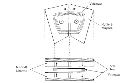
Figure 6.26. A flat voice-coil actuator for a personal computer disk drive
Moving - coil loudspeakers have been built with permanent magnets for over 70 years. Flux is directed into a radial air - gap where the voice coil is suspended, attached to a light, rigid cone (figure 6.3). As the current passes through the coil, the force on it is proportional to \(B_{\text{r}}\). The coil moves, vibrating the cone, which produces sound. The acoustic power \(P_{a}\) varies as \(B_{\text{r}}^{2}\). From (6.3), this is maximized by operating at the \((BH)_{\text{max}}\) point of the magnet. Good results are obtained when the flux density in the gap exceeds about \(0.5\ T\) and the mass of the voice coil is less than a gramme. Large, flat ferrite ring magnets can be used with iron to concentrate the flux. These designs are cheap but inefficient as there is much flux leakage; the flux loss factor \(\beta\approx0.4\). Stray fields are reduced in the cylindrical magnet designs using rare - earth or alnico magnets. Moving - magnet designs are feasible using Nd - Fe - B, where the magnet is glued to the cone and a stationary drive - coil surrounds it.
Voice - coil actuators are essentially similar to a loudspeaker in design. They are used for head positioning in computer hard - disk drives and mirror positioning in laser scanners. Rapid dynamic response is assured by the low mass of the voice - coil assembly and the low inductance of the coil in the air - gap. With
a cylindrical coil, radially magnetized ring magnets can be used to enhance the flux density in the air - gap. A common, flat - coil configuration is shown in figure 6.26. Here the coil is attached to a lever which allows it to swing in a limited arc between two pairs of rare - earth magnets. The design is favoured for the flat disk drives of portable personal computers and it requires Nd - Fe - B with the highest possible energy product (about \(400\ kJ\ m^{-3}\)). The access time at constant acceleration \(a\) is proportional to \(a^{-1/2}\) and hence to \(B_{\text{r}}^{-1/2}\), since \(F = B_{\text{r}}Il = m a\) (table 6.2).
Moving - coil meters are rotating - coil actuators with no stringent dynamic response requirement, but a very uniform air - gap flux density is needed to achieve a deflection which is accurately proportional to current. The requirement that there should be minimal temperature variation of the flux density leads to the choice of alnico in this application (table 6.2).
Moving - magnet actuators may be of the linear or rotating variety. They offer low inertia and no flying leads. Linear reciprocating actuators with a stroke of several millimetres are used in pumps at frequencies of the order of \(50\ Hz\). The operating frequency is designed to correspond to the resonant frequency of the mechanical system. Rotary actuators can be regarded as electric motors with restricted travel.
Moving - iron actuators may again be linear or rotary. A design for a print hammer for a dot - matrix printer is shown in figure 6.27(a). The hammer spring forms part of the magnetic circuit and in the unexcited position it is held tight against the iron, with no air - gap. When a current pulse passes through the solenoid, the hammer springs out. A similar principle is used in reed switches, where two flat soft iron reeds are drawn into contact by a magnetic field (figure 6.27(b)). The switch can be opened by activating a solenoid to create a reverse field or simply by moving the magnet.
Magnetic Motors: Driving Innovation in Electric and Mechanical Systems
Motors, generators and actuators whose operation depends on permanent magnets are produced in huge quantities, exceeding \(10^{8}\) units/year. A household which owned three motors 50 years ago may now possess a hundred or more of them in domestic appliances, audio, video and computer equipment, clocks, watches, toys and the car. Many of these are small dc permanent - magnet motors. De servomotors are found in machine tools, robots and other industrial machinery. Permanent magnets can also be used to advantage in large industrial drives, bringing savings in weight, energy and material costs. If electric vehicles ever become a widespread reality, yet more magnets will enter our daily lives. The ability to fabricate ferrite or rare - earth magnets in any desired shape has led to many permutations on a few basic electrical machine designs. One limitation is the maximum operating temperature of high remanence grades of Nd - Fe - B and ferrite which cannot match the running temperatures of many classical induction motors (table 6.2).
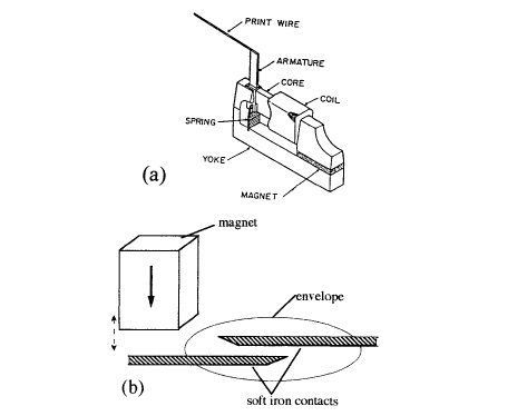
Figure 6.27. Moving - iron actuators: (a) a print hammer and (b) a reed switch.
The two main parts of a rotary machine are the fixed stator and the revolving rotor. The induction motor is an ac machine where the stator is an electromagnet with one or more pairs of poles. The term 'pole' refers to a region of hard or soft material magnetized normal to the air - gap where there is a surface charge \(\sigma\). Changing flux density in the stator created by alternating current, single or three - phase, induces eddy currents in the rotor and the forces on these currents in the field \(B\) cause the rotor to turn. The simplest rotor is just an iron cylinder, but standard designs have short - circuited copper windings or a cage arrangement of copper bars in which the eddy currents flow (figure 6.32).
Dc Motors
Many dc motor designs include both permanent magnets and electromagnet current windings. A common design is shown in figure 6.28(a). The permanent magnet on the fixed outer section, which is known as the stator, creates a field at the current - carrying windings of the rotor. A mechanical commutator with brushes distributes current to the windings in such a way that the torque \(\Gamma\) on the rotor is always in the same sense. Inversely, the device will also function as a generator, producing an emf \(U\) in the windings if it is driven at an angular
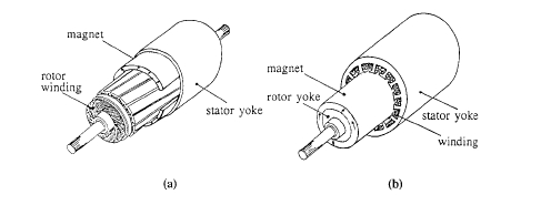
Figure 6.28. Dc motor designs: (a) a brush motor with magnets on the stator and (b) a brushless motor with magnets on the rotor.
velocity \(\omega\). The torque characteristic \(\Gamma(\omega)\) of the dc motor is rather simple. If the radius of the rotor winding is \(r\), the flux density of the magnet is \(B\) and there are \(n\) conductors of length \(L\) perpendicular to \(B\), each carrying a current \(I\), then \(\Gamma = nrBIL\). The output power \(P = \Gamma\omega\) will be equal to \(UI\), where the back emf \(U\) generated as the rotor turns is \(2r\omega BL\) per conductor. The number of conductors connected in series is \(n/2\), so \(U = nr\omega BL\). If the applied voltage is \(V = U+RI\), where \(R\) is the resistance in the windings, the torque equation for the motor is \[\Gamma = K(V - K\omega)/R\] (6.15) where \(K = nrBL\) is the torque constant of the motor. It may be seen from equation (6.15) that the torque is greatest at start - up, when \(\omega = 0\) and is proportional to the flux density produced by the magnet. It falls to zero when \(V = K\omega\).
In a dc servomotor, the torque or the angular velocity is controlled by modifying the applied voltage. Simple velocity control is based on monitoring the back emf \(U\), but more sophisticated control systems use a tachogenerator (a small dc generator coupled to the drive shaft) or a precise position encoder to generate a voltage feedback to control the output power.
The motor design may be modified, as shown in figure 6.29(b), to eliminate the mechanical commutator which is a source of sparking and wear. In the brushless dc motor, the magnets are situated on the rotor and the armature windings, now located on the stator, are energized in an appropriate sequence by means of power electronics. Electronically commutated motors are reliable and they are particularly suited to high - speed operation, \(\omega>100\ rad\ s^{-1}\) (\(>1000\ rpm\)). Position sensors form an integral part of the device since the winding is energized depends on the position of the rotor.
Some variants of the design of the brushless dc motor (Hanitsch 1996) are shown in figure 6.30. By unrolling the armature, a linear motor is obtained. Flattening the rotor into a disk produces a pancake motor. The low moment
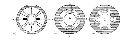
Figure 6.29. Motors: (a) a two - pole dc brush motor, (b) a two - pole four - phase brushless dc motor and (c) a variable - reluctance motor.
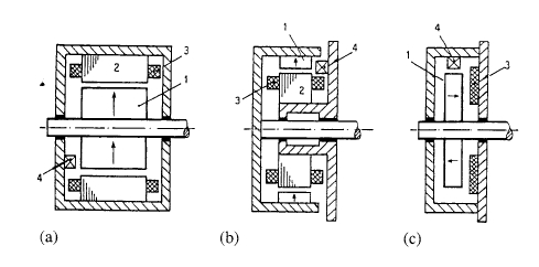
Figure 6.30. Variants of the brushless dc motor: (a) normal design, (b) cup - type and (c) disk - type. 1, magnet; 2, stator; 3, stator winding; 4, position sensor.
of inertia means that high angular accelerations are possible, especially when Nd - Fe - B is used for the magnets. They may be embedded in the rotor so as to concentrate the air - gap flux. The cup - type rotor is another low - inertia design.
A feature of all permanent - magnet motors is armature reaction. The currents in the armature, regardless of whether the armature windings are on the stator or on the rotor, create a field which is usually in a direction opposed to the magnetization. The working point of the magnets is shifted, as shown in figure 6.2. The effect is particularly severe at the trailing edges of the poles and a solution may be to make these sections from a high - coercivity grade magnet, as indicated in figure 6.31.
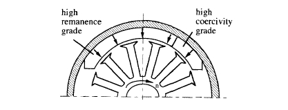
Figure 6.31. Modification of the magnets on the stator of a brushed dc motor of the type shown in figure 6.29(a) to cope with armature reaction.
Synchronous Motors
A synchronous motor runs at a frequency proportional to that of an ac power supply. Previously, operation was restricted to a multiple of the mains frequency determined by the number of poles on the stator, but electronic power inverters are now available which will run the motor at a continuously variable frequency.
The basic design is that of figure 6.28(b), where a magnet is on the rotor and a multiphase winding on the stator produces a field which rotates around the air - gap. Torque is proportional to \(\sin\delta\), where \(\delta\) is the angle at any instant between the flux produced by the stator and the direction of magnetization of the rotor. A multipole rotor may be produced by embedding long magnets of different orientations. By using these large embedded segments it is also possible to concentrate flux in the air - gap, producing a greater flux density than would be possible with a configuration where the magnets face the gap.
Synchronous motors offer high efficiency and power density, but their weak point is feeble starting torque until they get up to synchronous rotation speed. A classical induction motor with a squirrel - cage winding on the rotor to the opposite characteristic; the torque is maximum at start - up and falls to zero as the rotor approaches the angular velocity of the rotating field produced by the stator. There is then no changing flux in the squirrel - cage winding, hence no induced current and no force. Features of both motors can be combined. The rotor in figure 6.32 incorporates a 16 - bar cage winding with the bars connected to conducting plates at the top and bottom to help start - up.
Linear synchronous motors have been developed for Maglev systems where the magnets mounted on the vehicle are used for both lift and drive.
Generators
Most motor designs can operate as generators in an inverse mode. The rotor is driven, exposing the armature windings to a time - varying magnetic field, thus generating an emf. The bicycle dynamo was an early permanent - magnet application. Large disk - type machines with many permanent - magnet poles
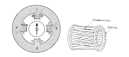
Figure 6.32. A four - pole synchronous motor with a permanent - magnet rotor. A 16 - bar squirrel - cage winding is incorporated so that the machine will operate as an induction motor for start - up.
(24 - 36) are well suited for wind energy conversion. The alternator for the hybrid electric vehicle may also use a permanent - magnet design. Operating at 100 000 rpm, a 30 kW generator is expected to have a mass of about 10 kg.
Stepping Motors
A stepping motor is a device which rotates through a fixed angle when one of the windings is energized by a suitable electronic control circuit. A simple two - pole motor is illustrated in figure 6.33. Stepping motors are used for precise position control. The motor shown in figure 6.29(b) could be used as a stepping motor, advancing by \(\pi/2\) as subsequent phases are energized. It is even possible to build such a motor using a soft - iron rotor with no permanent magnet whatsoever, as shown in figure 6.29(c). This variable - reluctance motor has salient poles on the rotor (six in the figure) and a rotor with a smaller number of protrusions or 'teeth' (four in the figure). The rotor turns by \(30^{\circ}\) as different pairs of windings are activated. A combination of high efficiency and small step is achieved by combining the variable - reluctance and permanent - magnet stepping motors in the hybrid stepping motor, as illustrated in figure 6.34. There are six poles, with five teeth on each. The rotor has 32 teeth with a permanent magnet at the centre. As the poles are energized in sequence, the motor turns in steps of 1/64th of a revolution. A common design makes 200 steps per revolution, a \(1.8^{\circ}\) step size. With a suitable controller, it will proceed in half - steps of \(0.9^{\circ}\).


